Shock wave therapeutic instrument

A technology of shock wave and therapeutic instrument, which is applied in the field of medical equipment, can solve the problems of increasing the risk of side effects, difficulty in locating the lesion, and poor treatment accuracy, so as to improve the treatment experience, shorten the treatment time, and reduce the side effects

Pending Publication Date: 2020-02-11
徐州康良电子科技有限公司
View PDF0 Cites 2 Cited by
  • Summary
  • Abstract
  • Description
  • Claims
  • Application Information

AI Technical Summary

Problems solved by technology

[0003] When using shock wave therapy equipment in daily life, it is often difficult to locate the location of the lesion. Due to the limitation of the positioning device of the instrument, the treatment time is too long, the treatment accuracy is poor, and unsafe accidents of accidental injury are prone to occur.
In addition, poor dose control of shock waves can also increase the risk of side effects

Method used


Image

  • Shock wave therapeutic instrument
  • Shock wave therapeutic instrument

Examples


Embodiment 1

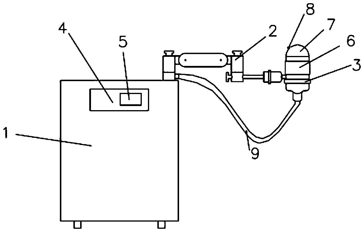
[0021] Such as figure 1 As shown, a shock wave therapeutic apparatus includes: a host 1, a movable arm 2, and a shock wave source 3, and a control terminal 4 is arranged on the host, and the control terminal 4 is connected to the shock wave source 3 through a wire. The shock wave source 3 is installed on the outer end of the movable arm 2, and the movable arm 2 is a two-section arm. The shock wave source 3 can move up and down, left and right and rotate through the linkage of the movable arm 2. This setting improves the flexibility of the movable arm, and satisfies the treatment of the lesion by the shock wave source 3 in different directions.

[0022] The control terminal 4 has an intelligent control module 5 which stores parameter information to control the frequency and intensity of the shock wave generated by the shock wave source 3 . Through the control terminal 4, the operator can complete the setting of all treatment parameters and treatment feedback.

[0023] An elec...

Embodiment 2

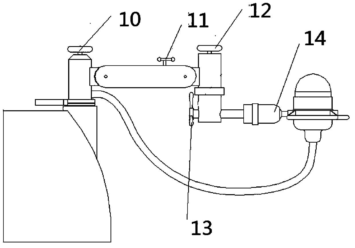
[0031] Such as Figure 1-2 As shown, the movable arm 2 is mainly used to control and adjust the position of the shock wave source 3 in space, and is used to contact and fix the shock wave source 3 at the spatial position to be treated by the patient.

[0032] The first section arm of movable arm 2 in the present embodiment is fixed on the host machine 1 by handwheel one 10, and handwheel one 10 is movably connected with handwheel two 12 by two hinges, so that the first section arm can Move up and down, and can also move in the horizontal direction with the handwheel 10 as the axis. The handwheel 10 is used to lock and unlock the position of the first section arm in the horizontal direction, and the wrench 11 is used to lock and unlock the hinge. It is thereby possible to lock and unlock the position of the first section arm in the vertical direction. The second arm is a sleeve, which is movably connected with the hand wheel 12. The sleeve can move left and right along the hor...


PUM


Abstract

The present invention discloses a shock wave therapeutic instrument. The shock wave therapeutic instrument comprises a main engine, a movable arm and a shock wave source, the main engine is provided with a control end, the control end is connected with the shock wave source through an electric wire, a water inlet pipe is also connected between the main engine and the shock wave source, the shock wave source is arranged at an outer end of the movable arm, the movable arm is a two-section arm, and the shock wave source realizes three modes of movements of moving up and down, and left and right and rotating through linkage of the movable arm. An intelligent control module is arranged in the control end and stores parameter information so as to control frequency and intensity of shock waves generated by the shock wave source. An electromagnetic shock wave generating device is arranged in the shock wave source, a water bag is arranged at an output end of the shock wave source, and the waterbag contacts with an electromagnetic shock wave generating device to conduct the shock waves to act on a disease focus of a patient. The shock wave therapeutic instrument has remarkable advantages ofeasiness in mastering, safety, flexibility, convenience, light side effect, etc.

Description

technical field [0001] The invention relates to the field of medical instruments, in particular to a shock wave therapy instrument. Background technique [0002] Shock waves are widely used in the field of medical equipment technology. They are mainly used in the treatment of acute and chronic soft tissue pain such as sports injuries and strains in the human body. They are easy to use, painless, and avoid adverse reactions of taking or injecting drugs. [0003] When using shock wave therapy equipment in daily life, it is often difficult to locate the location of the lesion. Due to the limitation of the equipment positioning device, the treatment time is too long, the treatment accuracy is poor, and unsafe accidents of accidental injury are prone to occur. In addition, poor dose control of shock waves can also increase the risk of side effects. Contents of the invention [0004] The object of the present invention is to solve one of the above-mentioned technical problems a...

Claims


Application Information

Patent Timeline
Patent Type & Authority Applications(China)
IPC IPC(8): A61H23/00A61H23/02
CPCA61H23/008A61H23/02A61H2201/14A61H2201/5005
Inventor 樊连民
Owner 徐州康良电子科技有限公司
Why Eureka
Try Eureka