Trajectory Tracking Method for Welding

A trajectory tracking and trajectory technology, which is applied in welding equipment, arc welding equipment, manufacturing tools, etc., can solve the problems affecting the control accuracy and stability, and the accuracy of measurement data, so as to achieve high-precision control and tracking, and stable and reliable data Effect

Active Publication Date: 2021-12-03
ZHEJIANG JINHUA JUNENG ELECTRONICS TECH
View PDF7 Cites 0 Cited by
  • Summary
  • Abstract
  • Description
  • Claims
  • Application Information

AI Technical Summary

Problems solved by technology

The existing tracking device will greatly affect the accuracy of its measurement data due to the influence of the surface of the welding plate or the external light, especially the arc light of welding, during welding, which will affect the control accuracy and stability.

Method used


Image

  • Trajectory Tracking Method for Welding
  • Trajectory Tracking Method for Welding
  • Trajectory Tracking Method for Welding

Examples


Embodiment

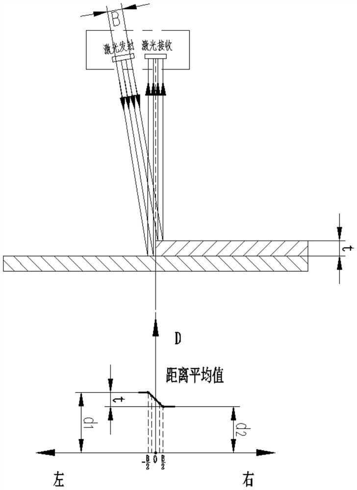
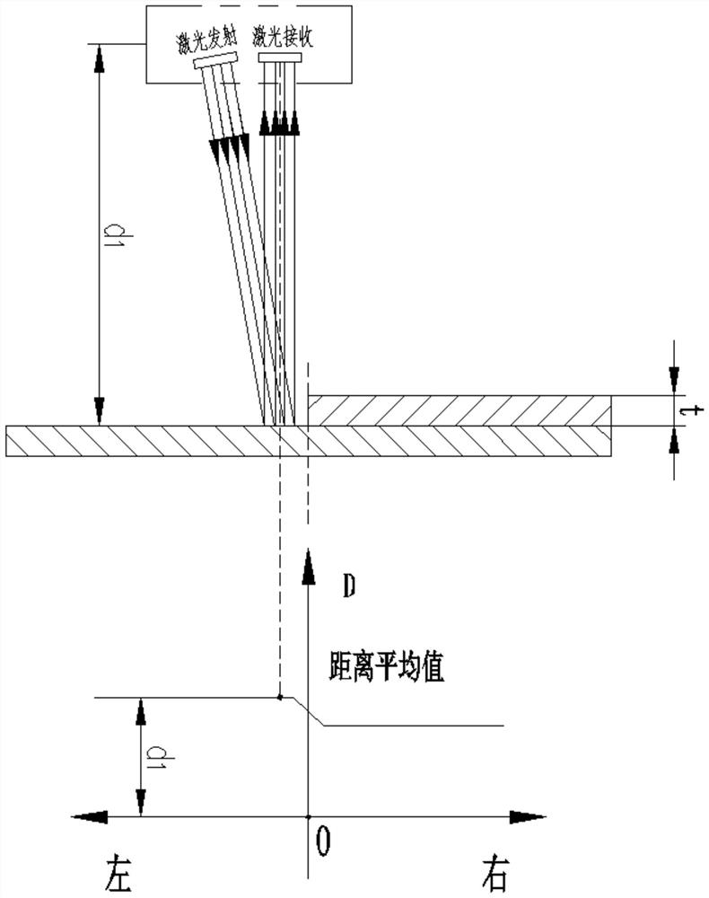
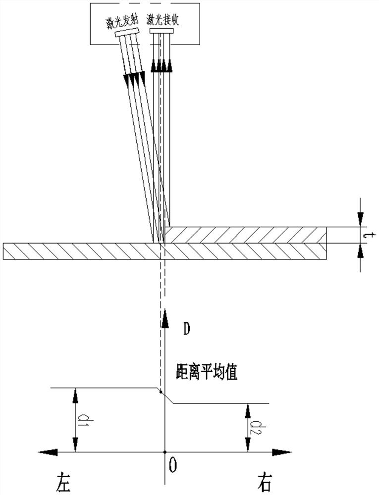
[0026] The trajectory tracking method for welding uses a single laser beam to irradiate the weld seam of the welded plate along the length of the weld seam; the laser beam is reflected from the weld seam and the areas on both sides of the weld seam to the photosensitive element to generate corresponding electrical signals. The measurement principle of single-point laser triangulation is to calculate the distance between the laser generating device and the welding plate, and calculate the average value of the distance measured by a single laser beam as D. If the average distance D is greater than the distance between the laser generating device and the bottom plate surface The arithmetic mean of the distance d1 and the distance d2 from the laser generating device to the surface of the top plate, that is, D>(d1+d2) / 2, the laser beam will shift to the left side of the plate from the weld track to the bottom; if the average distance D If it is less than the arithmetic mean value of...


PUM


Abstract

The invention discloses a welding track tracking method. A single laser beam is used to irradiate the weld along the length direction of the weld, and the laser beam is reflected to the photosensitive element through the weld and the areas on both sides of the weld to generate corresponding electrical signals. Using the measurement principle of single-point laser triangulation, calculate the distance between the laser generating device and the welding plate, and measure the average value of the entire laser beam distance, and judge whether the welding track is offset by the average value of the distance; when the welding track exists When offset, the signal is fed back to the position adjustment mechanism on the welding machine to adjust the welding track. The present invention utilizes the height difference when the ranging laser beam moves from one side of the weld to the other side, resulting in different average values ​​and a linear change interval, and judges the offset of the welding track according to the average height difference, which is in the process of measurement It will not be affected by external light, especially the intensity of welding arc light, the measured data is stable and reliable, and has the actual application conditions of welding tracking.

Description

technical field [0001] The invention relates to a trajectory tracking method for welding, in particular to a laser tracking method for welding trajectory. Background technique [0002] For the construction of Mark Ⅲ membrane LNG ship, it is necessary to implement high-precision automatic welding for a large number of lap welds of corrugated plates with a thickness of only 1.2mm. A high-precision weld seam tracking system with a control accuracy of more than 0.1mm is required. [0003] At present, the seam tracking measurement is to detect the offset in real time when the seam is being welded, and then transmit the measurement information of the seam to the welding actuator, and adjust the position of the welding torch or seam through the deviation correction mechanism, so that the two always maintain Appropriate relative positional relationship. Existing high-precision trajectory tracking methods for welding are generally divided into two types: contact and non-contact. Am...

Claims


Application Information

Patent Timeline
Patent Type & Authority Patents(China)
IPC IPC(8): B23K9/127
CPCB23K9/1274
Inventor 吕贤红邵献明
Owner ZHEJIANG JINHUA JUNENG ELECTRONICS TECH
Why Eureka
Try Eureka