
Third rail independent grounding system applicable to high-speed train

A technology for grounding systems and high-speed trains, applied in the field of third-rail independent grounding systems, can solve problems such as inconsistent grounding methods and grounding parameter settings, inability to effectively release overvoltages, and uniform grounding methods and grounding parameters. The effect of curbing the sharp rise of vehicle body voltage, ensuring safe and reliable operation, and reducing abnormal error reporting and damage

Inactive Publication Date: 2020-02-11
SOUTHWEST JIAOTONG UNIV
View PDF5 Cites 4 Cited by
  • Summary
  • Abstract
  • Description
  • Claims
  • Application Information

AI Technical Summary

Problems solved by technology

If the grounding point and grounding parameters are not selected properly, the overvoltage will not be effectively released; and if the positions of the protective grounding and the working grounding are not selected properly, the traction current released by the working grounding may be transmitted to the vehicle body through the protective grounding. The electric potential of the car body rises, posing a threat to personnel and vehicle weak current control equipment
[0006] At present, there is no uniform grounding method and grounding parameter setting, even for vehicles of the same model, the grounding method and grounding parameters have not yet been unified, so it is urgent to find an optimal high-speed train grounding method

Method used


Image

  • Third rail independent grounding system applicable to high-speed train
  • Third rail independent grounding system applicable to high-speed train
  • Third rail independent grounding system applicable to high-speed train

Examples


Embodiment Construction

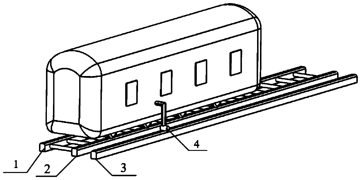
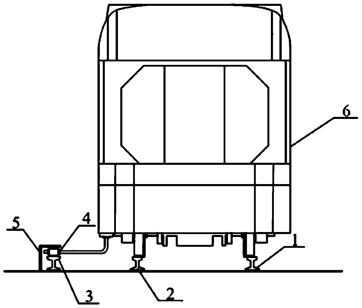
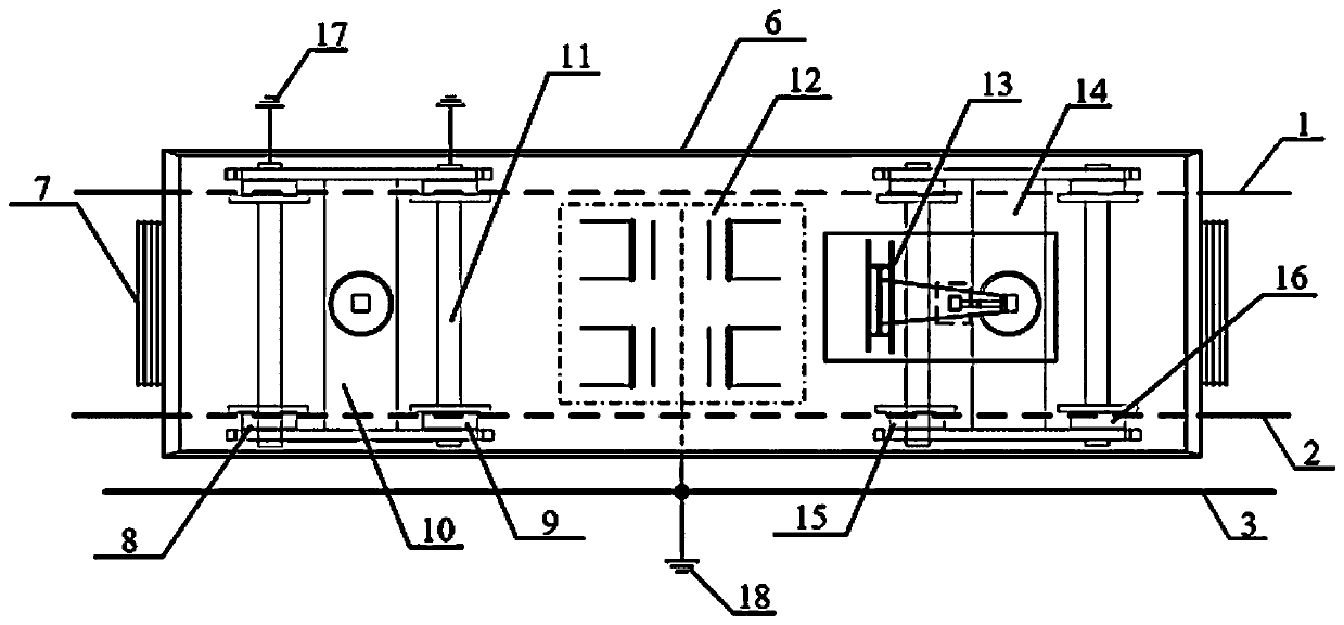
[0018] The present invention will be described in further detail below in conjunction with the accompanying drawings and specific embodiments. A new third-rail independent grounding method suitable for high-speed trains, the schematic diagram and cross-sectional view of the train and the grounded third rail are as follows figure 1 , figure 2 shown. The grounding system of the EMU is divided into working grounding and protective grounding. The backflow method of the working grounding system is as follows: image 3 ——Transformer compartment grounding top view, Figure 4 ——As shown in the main circuit diagram of the working grounding system, the working grounding system includes the third grounding rail 3, which is parallel to the two steel rails 1 and 2 and arranged outside the two steel rails 1 and 2, and the EMU passes through the pantograph 13 and Catenary contact, to obtain the traction current, after passing through the vacuum circuit breaker 24, the primary side of th...


PUM


Abstract

The invention discloses a third rail independent grounding system applicable to a high-speed train. The system comprises a working grounding system and a protection grounding system; the working grounding system comprises a grounding third rail, the grounding third rail is parallel to two steel rails and is arranged on the outer sides of the two steel rails, a train pantograph sequentially passesthrough a vacuum circuit breaker, the primary side of a vehicle-mounted transformer and the primary side of a main transformer and then is in rolling connection with the grounding third rail through afirst roller grounding carbon brush, so that working current flows back to a traction substation through the grounding third rail; and the protection grounding system comprises a second roller grounding carbon brush, and a train bogie and a train body are connected with the steel rails in a rolling mode through the second roller grounding carbon brush and wheels, so that leakage current flows back to the traction substation through the steel rails. The rail circulation phenomenon of a motor train unit can be effectively improved, the vehicle-mounted weak current equipment is prevented from being damaged by lifting the voltage of the train body due to the rail circulation, the counterattack on the weak current equipment by overvoltage generated by lightning stroke impact and bow lifting surge is prevented, and the safety and reliability of the operation of the motor train unit are improved.

Description

technical field [0001] The invention relates to the technical field of electric safety for high-speed trains, in particular to a third-rail independent grounding system suitable for high-speed trains. Background technique [0002] As a key part of the high-speed railway operating system, high-speed EMUs are of paramount importance to their safety and stability. As the operating speed of high-speed trains in my country continues to increase, the demand for traction power continues to increase, and the requirements for the EMU grounding system are getting higher and higher. The unreasonable grounding method and parameter design of the EMU will seriously cause serious damage to the safe operation of the EMU. For example, abnormal wear of grounding carbon brushes, rise in vehicle body potential, error reporting or even burning of vehicle sensors. [0003] According to the grounding method and functional characteristics, the grounding of EMUs can be divided into two types: one is...

Claims


Application Information

Patent Timeline
Patent Type & Authority Applications(China)
IPC IPC(8): B60M5/02
CPCB60M5/02
Inventor 肖嵩张灿孟举赖新安叶智宗童梦园李玉航吴京驰罗远培饶阳高国强吴广宁
Owner SOUTHWEST JIAOTONG UNIV
Learn More