Bionic-based flying mechanical neck eye system and control method

A control method and mechanical technology, applied in attitude control, aircraft parts, control/adjustment systems, etc., which can solve the problems of inability to avoid failure environment and incomplete environment observation.

Active Publication Date: 2020-02-11
HARBIN INST OF TECH SHENZHEN GRADUATE SCHOOL
View PDF10 Cites 4 Cited by
  • Summary
  • Abstract
  • Description
  • Claims
  • Application Information

AI Technical Summary

Problems solved by technology

[0007] The cameras in the above-mentioned patents are all connected to the airframe. The above-mentioned system will be limited by the position of the airframe during the flight of the indoor narrow scene, resulting in incomplete observation of the environment, and it is impossible to avoid certain failure environments.

Method used


Image

  • Bionic-based flying mechanical neck eye system and control method
  • Bionic-based flying mechanical neck eye system and control method
  • Bionic-based flying mechanical neck eye system and control method

Examples


Embodiment Construction

[0048] In order to make the object, technical solution and advantages of the present invention more clear, the present invention will be further described in detail below in conjunction with the examples, but the protection scope of the present invention is not limited to the following specific examples.

[0049] System embodiment

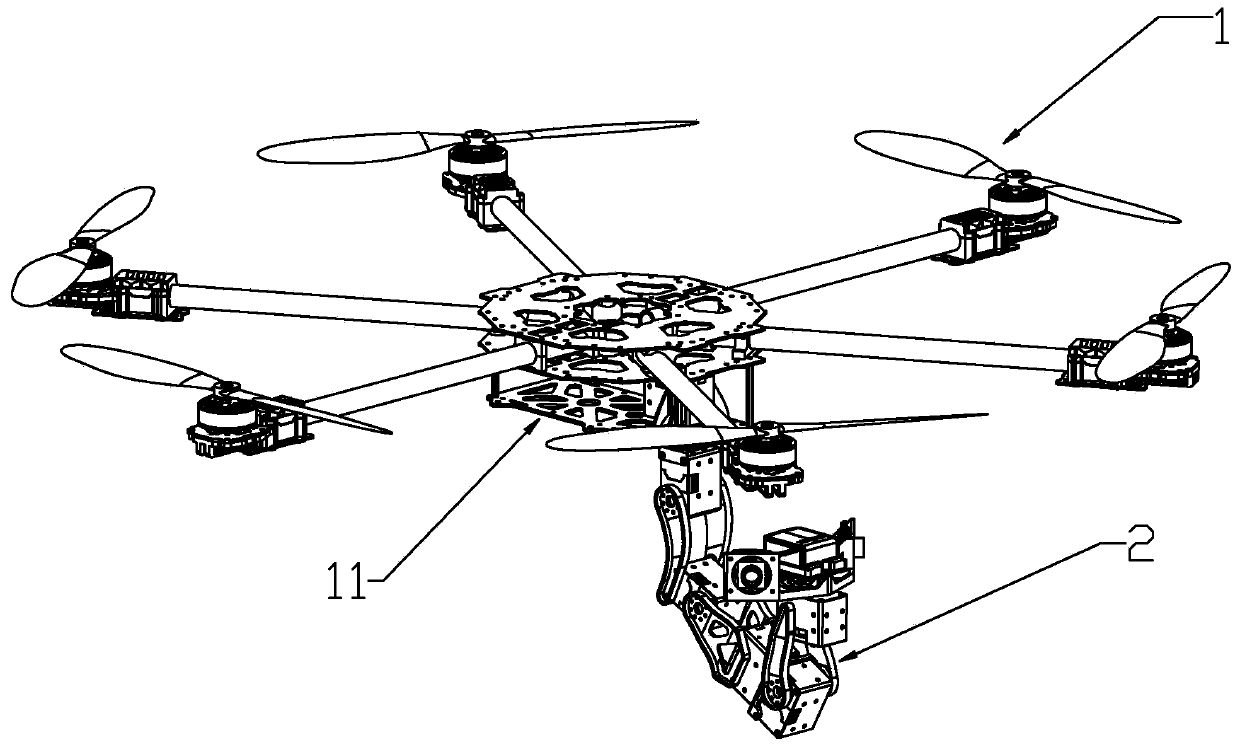
[0050] Such as figure 1 and 4 As shown, a bionic-based flight mechanical neck-eye system 2 includes an aircraft system 1, a mechanical neck-eye system 2, an airborne computing device and a flight control unit;

[0051] The aircraft system 1 includes an aircraft body and a flight power system installed on the aircraft body;

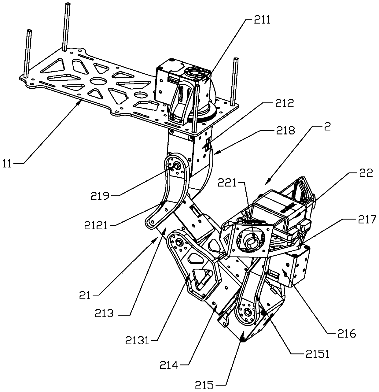
[0052] The mechanical neck-eye system 2 includes a mechanical neck 21 installed on the aircraft body, a binocular vision-inertial system 22 installed at the end of the mechanical neck 21, and a mechanical neck main controller that controls the movement of the mechanical neck 21; The binocular visual-inertial system 22 includ...


PUM


Abstract

The invention discloses a bionic-based flying mechanical neck eye system and a control method thereof. The system involves an aircraft system, a mechanical neck eye system, an airborne computing device and a flight control unit; the mechanical neck eye system involves a mechanical neck arranged on an aircraft body, a binocular vision inertia system arranged at the tail end of the mechanical neck,and a mechanical neck main control for controlling the movement of the mechanical neck; and the binocular vision inertial system involves a binocular camera and an inertial measurement unit, the binocular vision inertia system is used for carrying out active observation and completing pose estimation on the tail end of the mechanical neck, and the mechanical neck is a six-degree-of-freedom seriesmechanical neck. According to the bionic-based flying mechanical neck eye system and the control method thereof, the binocular vision inertial system consisting of the double fisheye cameras and the inertial measurement unit is placed at the tail end of the mechanical neck to form a sensing system, so that the observation range of the system is larger; and the cameras is variable in pose, and hasthe capability of actively sensing the environment, so that the problem that the view field of an aircraft in the indoor environment is limited can be solved to a certain extent, and meanwhile, the shaking of pictures can be compensated.

Description

technical field [0001] The invention relates to the field of unmanned aerial vehicles, in particular to a bionic-based flying machine neck-eye system and a control method. Background technique [0002] UAVs have a wide range of space movement capabilities and fast response capabilities, so they are widely used in military, agricultural, inspection and other fields. In recent years, people have begun research on flying robotic arms. The robotic arm is installed on the body of the multi-rotor unmanned aerial vehicle to achieve more complex and multi-degree-of-freedom operations. [0003] Since the image sensor used by the multi-rotor aircraft to perceive the environment autonomously is usually connected to the aircraft body, cameras and other equipment are generally installed on the airborne gimbal to compensate for the angle shake of the aircraft body. However, this installation method is often limited by the position of the body when observing the environment, resulting in ...

Claims


Application Information

Patent Timeline
Patent Type & Authority Applications(China)
IPC IPC(8): B64D47/08G01C21/00G01C21/16G05D1/08G05D1/10
CPCB64D47/08G01C21/00G01C21/165G05D1/0816G05D1/101
Inventor 孙家弼帅俊陈浩耀刘云辉
Owner HARBIN INST OF TECH SHENZHEN GRADUATE SCHOOL
Why Eureka
Try Eureka