
A kind of combustor transition piece structure and outlet side connection method

A connection method and burner technology, which are applied to combustion methods, combustion chambers, combustion equipment, etc., can solve the problems of complicated design of unstable sealing structure at the exit of the transition piece, complex design of the sealing structure, and stability of transition of transition pieces, etc. Achieve the effect of good installation stability, good sealing effect and wide applicability

Active Publication Date: 2020-11-24
DONGFANG TURBINE CO LTD
View PDF7 Cites 0 Cited by
  • Summary
  • Abstract
  • Description
  • Claims
  • Application Information

AI Technical Summary

Problems solved by technology

However, there is no connection structure design on the side of the tailpiece outlet, which is more likely to cause the instability of the tailpiece outlet and the design of the sealing structure between two adjacent tailpieces is more complicated.
In order to solve the above problems, a special combustor transition structure design is adopted, which can effectively solve the problem of connection stability between two adjacent transition transitions and the complex design of the sealing structure.

Method used


Image

  • A kind of combustor transition piece structure and outlet side connection method
  • A kind of combustor transition piece structure and outlet side connection method
  • A kind of combustor transition piece structure and outlet side connection method

Examples


Embodiment 1

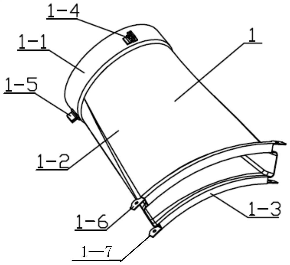
[0029] Such as figure 1 As shown, in this embodiment, a combustor tail tube structure is specifically provided, an important component of a gas turbine (aero engine) combustor, which includes a tail tube body 1-2, the tail tube body 1-2 As the main structure of the burner tail tube, a tail tube inlet support ring 1-1 is provided at one end of the tail tube body 1-2, and two tail tubes are provided in the circumferential direction of the tail tube inlet support ring 1-1 The inlet positioning structure (respectively the first tail tube inlet positioning structure 1-4, the second tail tube inlet positioning structure 1-5), through the tail tube inlet positioning structure for pre-positioning to ensure the correct installation of the combustor tail tube structure Preferably, in this embodiment, the tail cylinder inlet positioning structure is realized by a convex structure; the other end is provided with a tail cylinder outlet flange 1-3, and both sides of the tail cylinder outlet f...

Embodiment 2

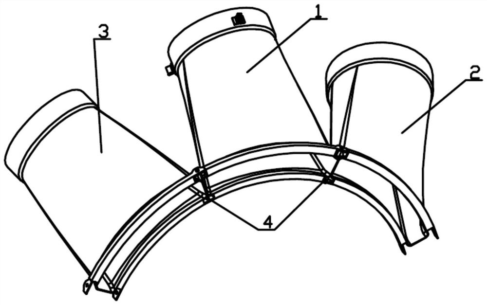
[0032] On the basis of Example 1, such as figure 2 As shown, in this embodiment, a method for connecting the outlet side of the combustor tail tube structure is specifically provided, and three of the above-mentioned combustor tail tube structures (respectively A combustor tail tube structure 1, B combustor tail Tube structure 2, C combustor tail tube structure 3), the outlet side connection method is as follows:

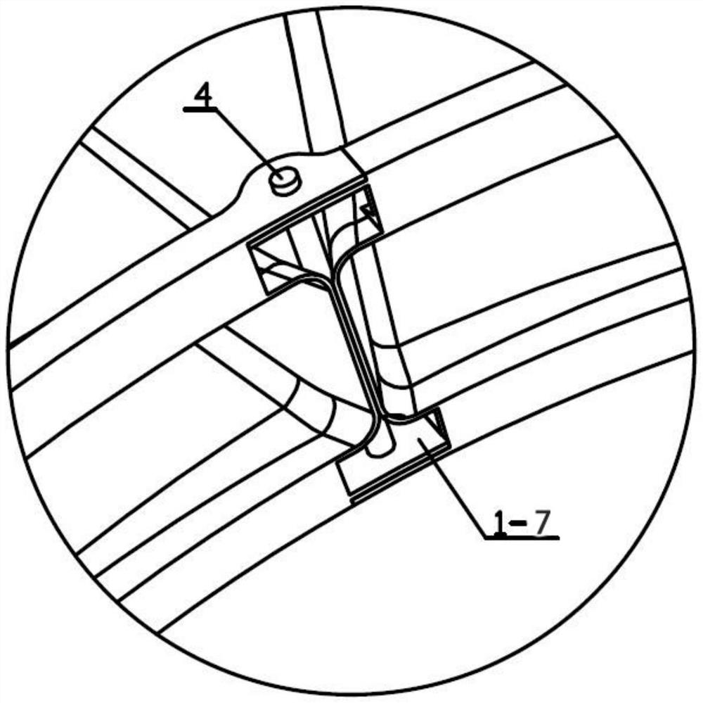
[0033] (1) Assemble each burner tail tube structure on the burner in turn. You can install one burner tail tube structure first, and then install the other two burner tail tube structures on both sides; three burners can also be installed. The tail tube structures are installed in sequence along the same lateral direction; after the installation of each combustor tail tube structure is completed, it is necessary to ensure that the first outlet connection structure and the second outlet connection structure of each combustor tail tube structure are arranged alternately;...


PUM


Abstract

The invention discloses a combustor tail piece structure and outlet lateral connection method, belonging to the field of gas turbines (aeroengines), comprising a tailpiece body, one end of the tailpiece body is provided with a tailpiece inlet support ring, and the other One end is provided with a tailpiece outlet flange, and the two sides of the tailpiece outlet flange are respectively provided with a first outlet connection structure and a second outlet connection structure along its tangential direction, and the first outlet connection structure and the second outlet connection structure Each burner transition structure is assembled on the burner in sequence, and the first outlet connection structure and the second outlet connection structure of each burner transition structure are arranged alternately; the adjacent first The first outlet connection structure is overlapped with the second outlet connection structure and locked by the connection pin. At the same time, a gap is formed between the transition tube bodies of two adjacent burner transition structures, and the gap is blocked and sealed by the connection pin. In order to achieve the purpose of significantly improving the connection stability and sealing performance of two adjacent tailpieces.

Description

Technical field [0001] The invention belongs to the technical field of gas turbines (aviation engines), and specifically relates to a combustor tail tube structure and an outlet lateral connection method. Background technique [0002] The combustor tail tube is an important part of the gas turbine (aero engine) combustor. It is a combustion diversion device made of high-temperature alloy materials and is one of the indispensable parts of the gas turbine (aero engine). The fuel converts chemical energy into heat energy through the combustion chemical reaction in the combustor flame tube to form high-temperature and high-pressure combustion products, which are quickly sprayed through the combustor tail tube to the high-temperature turbine (turbine) blades to drive the turbine (turbine) to do work and drive The generator generates external power and drives the gas turbine (aero engine) rotor to rotate at high speed to compress air. [0003] The combustor assembly of a gas turbine (ae...

Claims


Application Information

Patent Timeline
Patent Type & Authority Patents(China)
IPC IPC(8): F23R3/60
CPCF23R3/60
Inventor 刘维兵田晓晶凤云仙冯珍珍杨安建张渊黄毅艾松
Owner DONGFANG TURBINE CO LTD
Learn More