Control method for air source heat pump unit, electronic equipment, and computer-readable storage medium

An air source heat pump and unit control technology, which is applied in the direction of machinery and equipment, can solve the problems of unchanged maintenance work, increased power consumption, and lack of equipment, and achieve the effect of convenient troubleshooting and quick maintenance

Active Publication Date: 2020-02-11
GUANGDONG HIWAVE TECH
View PDF10 Cites 0 Cited by
  • Summary
  • Abstract
  • Description
  • Claims
  • Application Information

AI Technical Summary

Problems solved by technology

[0002] During the operation of the air source heat pump, in order to ensure the heating of the room, the heating capacity of the unit must be able to meet the heat load demand of the house. However, the structure of the unit of the existing air source heat pump is as follows: figure 1 As shown, only compressor 1, four-way valve 2, fan 3, outdoor refrigerant-air heat exchanger 4, outdoor temperature sensor 5, electronic expansion valve 6, liquid receiver 7, water-refrigerant heat exchanger 8. Composed of 9 gas-liquid separators, this structure d

Method used


Image

  • Control method for air source heat pump unit, electronic equipment, and computer-readable storage medium
  • Control method for air source heat pump unit, electronic equipment, and computer-readable storage medium
  • Control method for air source heat pump unit, electronic equipment, and computer-readable storage medium

Examples


Example Embodiment

[0034] Hereinafter, exemplary embodiments of the present disclosure will be described in more detail with reference to the accompanying drawings. Although exemplary embodiments of the present disclosure are shown in the drawings, it should be understood that the present disclosure can be implemented in various forms and should not be limited by the embodiments set forth herein. On the contrary, these embodiments are provided to enable a more thorough understanding of the present disclosure and to fully convey the scope of the present disclosure to those skilled in the art.
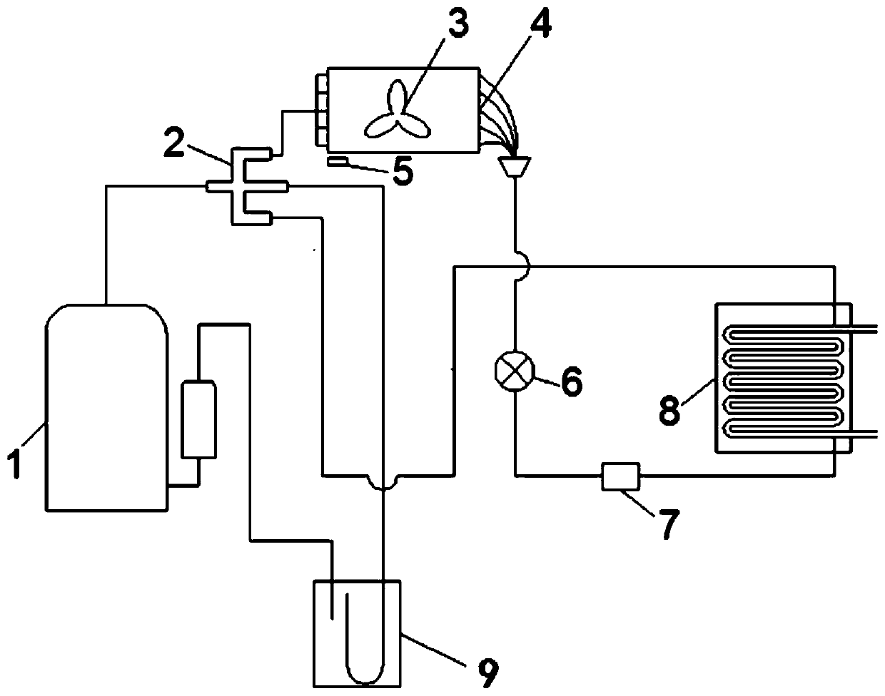
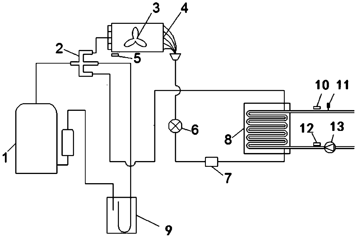
[0035] see figure 2 , The structural scheme of this example is based on the existing foundation, adding an outlet water temperature sensor 10 and a water flow meter 11 to the water outlet pipe of the water-refrigerant heat exchanger 8, and on the water inlet pipe of the water-refrigerant heat exchanger 8. The inlet water temperature sensor 12 and the circulating water pump 13 are added, and based on the abov...


PUM


Abstract

The present invention relates to a control method for an air source heat pump unit, electronic equipment, and a computer-readable storage medium. The control method, the electronic equipment, and thecomputer-readable storage medium are used to accurately obtain the real-time heating/cooling quantity in the unit for feedback, so that after-sales service personnel is convenient to carry out troubleshooting and achieve quick repair; the method includes the following steps performed sequentially: a real-time heating/cooling quantity Q monitoring step, which is used for monitoring the actual watertemperature T1 of the unit, and calculating the real-time heating/cooling quantity Q of the unit when the actual water temperature T1 is lower than the target water temperature T2; a warning step, which is for triggering the unit to give different types of warnings according to comparison results between the real-time heating/cooling quantity Q and the standard heating/cooling quantity Q1.

Description

technical field [0001] The invention relates to the field of air conditioning, and in particular to a control method for an air source heat pump unit, electronic equipment, and a computer-readable storage medium. Background technique [0002] During the operation of the air source heat pump, in order to ensure the heating of the room, the heating capacity of the unit must be able to meet the heat load demand of the house. However, the structure of the unit of the existing air source heat pump is as follows: figure 1 As shown, only compressor 1, four-way valve 2, fan 3, outdoor refrigerant-air heat exchanger 4, outdoor temperature sensor 5, electronic expansion valve 6, liquid receiver 7, water-refrigerant heat exchanger 8. Composed of 9 gas-liquid separators, this structure does not have the ability to accurately know the real-time heating / cooling capacity. Once the indoor temperature is too low / high, the unit will only blindly increase heating / cooling according to the tempe...

Claims


Application Information

Patent Timeline
IPC IPC(8): F24F11/64F24F11/52
CPCF24F11/52F24F11/64
Inventor 吴先应李丹李福水
Owner GUANGDONG HIWAVE TECH
Why Eureka
Try Eureka