Current density detection composite board and online detection device for current density in battery

A technology of current density and composite board, which is applied in the direction of current density measurement, measuring devices, measuring electricity, etc., can solve the problems of increasing the cost of detection devices, achieve the effects of improving reliability, reducing manufacturing difficulty, and good interchangeability

Pending Publication Date: 2020-02-11
SOUTH UNIVERSITY OF SCIENCE AND TECHNOLOGY OF CHINA
View PDF0 Cites 7 Cited by
  • Summary
  • Abstract
  • Description
  • Claims
  • Application Information

AI Technical Summary

Problems solved by technology

[0006] The purpose of the present invention is to provide a current density detection composite board to solve the technical problem existing in the prior art that different detection devices need to be replaced for different flow fields, resulting in increased cost of the detection device

Method used


Image

  • Current density detection composite board and online detection device for current density in battery
  • Current density detection composite board and online detection device for current density in battery
  • Current density detection composite board and online detection device for current density in battery

Examples


Embodiment 1

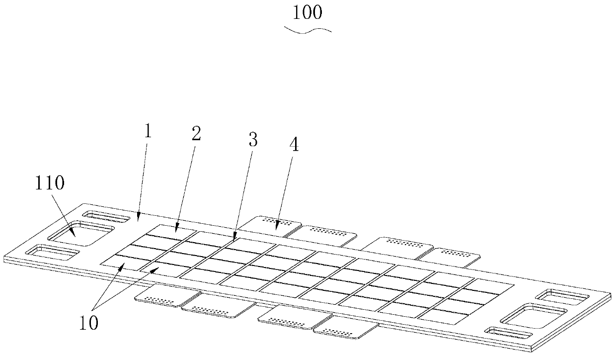
[0063] see Figure 6 to Figure 10 , the detection board 100 includes two first circuit boards 40 stacked, the first circuit board 40 has welding areas 41 distributed in a matrix, the welding areas 41 of the two first circuit boards 40 are distributed in one-to-one correspondence, the first circuit board 40 is provided with through holes 42 corresponding to the welding areas 41 one by one, and the through holes 42 of the two first circuit boards 40 are correspondingly connected; the first circuit board 40 is provided with circuit traces 43 correspondingly electrically connected to each welding area 41 , the first circuit board 40 is provided with a pin socket 44 at the end of the circuit trace 43; the board body 1 includes two insulating frames 10 stacked, each insulating frame 10 has a function for accommodating a first circuit board 40 Two first circuit boards 40 are respectively embedded and clamped between two insulating frames 10, and the insulating frame 10 is provided with...

Embodiment 2

[0076] The technical features of the current density detection composite board 1000 in this embodiment are basically the same as those of the current density detection composite board 1000 in Embodiment 1, the difference is that in this embodiment, please refer to Figure 11 , the standard resistor 22 is placed outside the board body 1 . Specifically, the conductive sheets 21 are separated by two second circuit boards 60, the two second circuit boards 60 are respectively embedded in the board body 1 and at least partly exposed outside the board body 1, and the two conductive sheets 21 are connected to the two second circuit boards respectively. The two circuit boards 60 are electrically connected, and each standard resistor 22 is respectively pasted on the part of the second circuit board 60 exposed outside the board body 1 .

[0077] In addition, the board body 1 can be composed of two insulating frames. At this time, the two second circuit boards 60 are attached to each othe...

Embodiment 3

[0079] The technical features of the current density detection composite board 1000 in this embodiment are basically the same as those of the current density detection composite board 1000 in Embodiment 1, the difference is that in this embodiment, please refer to Figure 12 , the plate body 1 is a single-layer structure, a second insulating member 23 is arranged between the two conductive sheets 21, and the standard resistor 22 is arranged on the side edges of the two conductive sheets 21; or, the standard resistor 22 is embedded in the second insulating member 23 or the standard resistor 22 is set on the third external circuit board, and the two ends are electrically connected to the two conductive sheets 21 through the second wire respectively; the two ends of the standard resistor 22 are connected with the first wire 24, and the external controller passes the first wire 24 is electrically connected with the standard resistance 22 to measure the voltage drop across the stand...


PUM


Abstract

The invention provides a current density detection composite board. The current density detection composite board comprises a detection board and a flow field board, wherein the detection board comprises a board body, a detection unit, a first insulating part and a circuit board or a first wire; the detection unit comprises two conductive sheets which are arranged at intervals, and standard resistors of which the two ends are connected to the two conductive sheets in a one-to-one correspondence manner; one side of the flow field board is connected with one side of the board body in a fitting manner and is conducted with one conductive sheet; and a runner is formed in the other side of the flow field board. An online detection apparatus for the current density in a battery comprises the current density detection composite board. According to the current density detection composite board provided by the invention, one detection board can be matched with different flow field boards, so that the purpose of performing current density detection on bipolar plates, anode plates and cathode plates with different designs and any position in an electric pile can be achieved; the current density detection composite board has very high interchangeability; and meanwhile, a gas isolation function is not needed, and the runner does not need to be processed on the conductive sheets of the detection unit, so that the manufacturing difficulty of the detection board is lowered.

Description

technical field [0001] The invention belongs to the technical field of fuel cell testing, and more specifically relates to a composite board for detecting current density and an on-line measuring device for detecting current density in a fuel cell. Background technique [0002] A fuel cell is a power generation device that directly converts the chemical energy in fuel into electrical energy through an electrochemical reaction. It has been more than 100 years since the fuel cell was invented. As energy and the environment have become key issues for the survival of human society, over the past 20 years, fuel cells, a highly efficient and clean energy conversion device, have received widespread attention from governments, developers and research institutions in various countries. Civil and military fields such as power supplies, distributed power stations, aerospace and underwater vehicles show broad application prospects. [0003] The current density inside the fuel cell is ...

Claims


Application Information

Patent Timeline
Patent Type & Authority Applications(China)
IPC IPC(8): G01R31/385G01R19/08
CPCG01R19/08G01R31/385
Inventor 王亚军冯其陈琼周嫦张小明李辉王海江
Owner SOUTH UNIVERSITY OF SCIENCE AND TECHNOLOGY OF CHINA
Why Eureka
Try Eureka