Profile steel welding robot system and working method thereof

A welding robot and robot technology, applied in welding equipment, auxiliary welding equipment, welding/cutting auxiliary equipment, etc., can solve the problems of lowering production efficiency and welding quality, such as breakdown, undercut, and no existing section steel welding device and method and other issues to achieve the effect of ensuring safety

Pending Publication Date: 2020-02-14
ZHONGTONG BUS HLDG
View PDF9 Cites 0 Cited by
  • Summary
  • Abstract
  • Description
  • Claims
  • Application Information

AI Technical Summary

Problems solved by technology

[0003] The inventor believes that due to the blanking accuracy and human factors during the welding of the section steel skeleton, the gap between the lap joints of the section steel will vary in the range of 0-2 mm, and welding quality problems will occur in the weld seam when the same welding process parameters are used for the gap between different groups. Such as breakdown, undercut and other problems, if the quality problems are solved by repair welding, grinding, etc., the production efficiency will be reduced
[0004] In the existing literature, there is no welding device and method specifically for section steel

Method used


Image

  • Profile steel welding robot system and working method thereof
  • Profile steel welding robot system and working method thereof

Examples


Embodiment 1

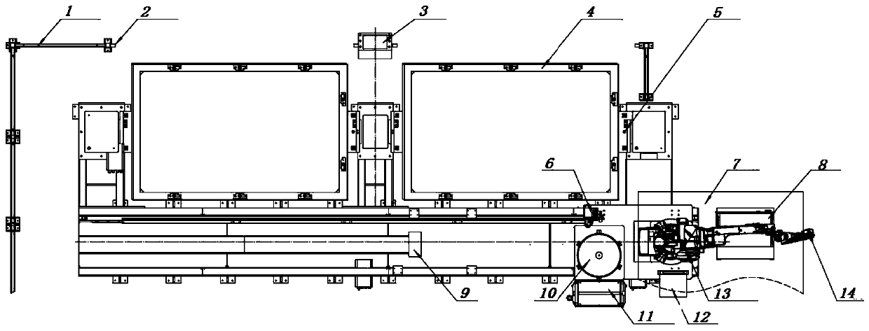
[0038] Please refer to figure 1 , the present embodiment discloses a steel welding robot 13 system, including a plurality of steel robot welding devices and a numerical control module connected to a plurality of steel robot welding devices, each steel robot welding device includes a safety protection mechanism, a welding robot 13, a robot Sliding table 9, welding auxiliary mechanism and laser sensor 14 installed in welding robot 13, welding robot 13, robot sliding table 9 and welding auxiliary mechanism are all placed on the inside of the safety protection mechanism, welding robot 13 is slidingly connected to robot sliding table 9; this implementation The numerical control module in the example is located in the robot control cabinet 8.

[0039] A plurality of welding robots 13 are placed in a constant temperature environment.

[0040] The robot is equipped with a welding torch.

[0041] Each of the welding robots 13 and each laser sensor 14 is connected to a numerical contr...

Embodiment 2

[0071] Embodiment 2 discloses a working method of a section steel welding robot 13 system, using the section steel welding robot 13 system as described in embodiment 1, comprising the following steps:

[0072] After the skeleton section steel is cut and blanked, the single-axis head and tail positioner tooling clamps the workpiece to be welded;

[0073] Make an appointment to start the welding robot 13;

[0074] After receiving the appointment signal, the robot enters the station and starts welding;

[0075] The single-axis head and tail positioner cooperates with the robot to flip and shift the workpiece, and the robot completes the welding;

[0076] After the welding program is completed, the robot resets and waits; or moves into the second station welding through the robot sliding table 9 .

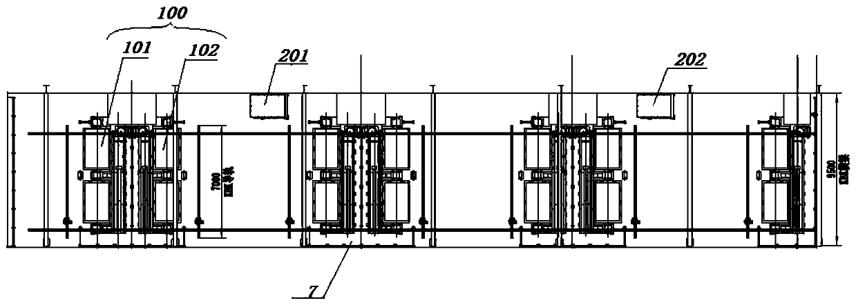
[0077] The two section steel robot welding devices of each group of robot welding workstations 100 can work independently or alternately.


PUM


Abstract

The invention discloses a profile steel welding robot system and a working method thereof. The profile steel welding robot system comprises a plurality of profile steel robot welding devices and a numerical control module connected with the profile steel robot welding devices, wherein each profile steel robot welding device comprises a safety protection mechanism, a welding robot, a robot slidingtable, a welding auxiliary mechanism and a laser sensor mounted on the welding robot; the laser sensor is used for measuring the distance between two pieces of profile steel to be welded, and the welding robot is in sliding connection with the robot sliding table; the welding robots, the robot sliding tables and the welding auxiliary mechanisms are all arranged on the inner sides of the safety protection mechanisms; and the welding robots are all arranged in a constant-temperature environment. According to the profile steel welding robot system and the working method thereof, on the premise ofachieving safety protection, the welding precision can be improved, and meanwhile the welding efficiency of the profile steel is improved.

Description

technical field [0001] The invention relates to the field of welding robots, in particular to a section steel welding robot system and a working method thereof. Background technique [0002] Sectional steel skeleton is a type of steel skeleton, which is a structure often used in the construction field, and it has good toughness. Because the building structure using steel frame often has a large volume, the profiles that make up the steel frame usually need to be welded to extend its length. In addition, because the steel structure usually has a relatively complex cross-sectional shape, the welding accuracy is relatively high. high. [0003] The inventor believes that due to the blanking accuracy and human factors during the welding of the section steel skeleton, the gap between the lap joints of the section steel will vary in the range of 0-2 mm, and welding quality problems will occur in the weld seam when the same welding process parameters are used for the gap between di...

Claims


Application Information

Patent Timeline
Patent Type & Authority Applications(China)
IPC IPC(8): B23K37/00B23K37/02B23K37/04
CPCB23K37/00B23K37/006B23K37/0252B23K37/0443
Inventor 于俊严囤金军曹德明王建虎吉学刚申子正任怀东张德兵
Owner ZHONGTONG BUS HLDG
Why Eureka
Try Eureka