Machining device for high-frequency welded pipe production

A technology for processing equipment and high-frequency welded pipes, applied in high-frequency current welding equipment, metal processing equipment, welding equipment, etc., can solve problems affecting welding quality, unbalanced extrusion force, uneven airflow, etc., and reduce fatigue resistance Intensity, gentle cooling, easy and effective

Inactive Publication Date: 2020-02-14
TIANJIN HONGREN METAL MATERIAL CO LTD
View PDF0 Cites 7 Cited by
  • Summary
  • Abstract
  • Description
  • Claims
  • Application Information

AI Technical Summary

Problems solved by technology

[0004] The object of the present invention is to provide a processing equipment for high-frequency welded pipe production, to solve the problem that the current processing equipment for high-frequency welded pipe production proposed in the above background technology will cause the cylindrical tube blank to be transported by the transport wheel. The vibration of the wheel or the conveying wheel causes the tube blank to rotate, and when the tube blank passes through the extrusion roller after heating, the weld seam is not at the center of the two extrusion rollers, resulting in the extrusion of the weld seam in the upper and lower directions. The unbalanced force greatly affects the quality of welding, resulting in too many burrs; and generally a cooling device is installed in the welding, but the air flow rate generated by the general fan is relatively fast, and the air flow is uneven, resulting in too fast cooling, which will cause the steel pipe to be damaged. Internal cracks and even deformation problems

Method used


Image

  • Machining device for high-frequency welded pipe production
  • Machining device for high-frequency welded pipe production
  • Machining device for high-frequency welded pipe production

Examples


Embodiment Construction

[0019] The following will clearly and completely describe the technical solutions in the embodiments of the present invention with reference to the accompanying drawings in the embodiments of the present invention. Obviously, the described embodiments are only some, not all, embodiments of the present invention. Based on the embodiments of the present invention, all other embodiments obtained by persons of ordinary skill in the art without making creative efforts belong to the protection scope of the present invention.

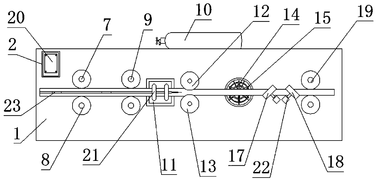
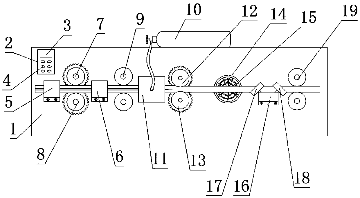
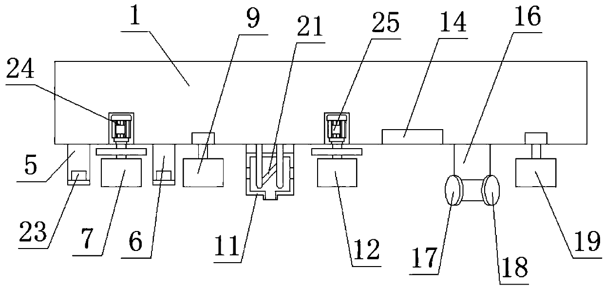
[0020] see Figure 1-6 , the present invention provides a technical solution: a processing equipment for high-frequency welded pipe production, including a body 1, the left end of the front surface of the body 1 is equipped with a first limit support plate 5 through bolts, and the right end of the first limit support plate 5 Driven conveying wheel 7 is provided with, and driven conveying wheel 8 is arranged on the below of active conveying wheel 7, and driving...


PUM


Abstract

The invention discloses a machining device for high-frequency welded pipe production. The machining device comprises a machine body, wherein a first limiting supporting plate is mounted at the left end of the front surface of the machine body through bolts; a driving conveying wheel is arranged at the right end of the first limiting supporting plate; and a driven conveying wheel is arranged belowthe driving conveying wheel. According to the machining device, two limiting plates are mounted in the feeding direction, the limiting plates can be inserted into edge gaps of a pipe blank, the pipe blank is prevented from rotating during conveying, so that when the pipe blank is extruded by an extrusion roller, the upper pressure, the lower pressure and the pressure direction are kept balanced, the welding quality is greatly guaranteed, and burrs are reduced; and an air guide disc is mounted on a cooling fan, the air guide disc can rotate under the blowing of airflow, the flow speed of the airflow is reduced due to the blockage of the structure of the air guide disc, the air supply area can be increased, the flow speed is more uniform, cooling is more gentle, internal cracks caused by toofast cooling are avoided, and the surface quality of a steel pipe is greatly maintained.

Description

technical field [0001] The invention belongs to the field of welding technology, and in particular relates to a processing equipment for high-frequency welded pipe production. Background technique [0002] High-frequency welded pipe is a steel pipe processed by high-frequency resistance welding. Its working principle is that the formed cylindrical tube blank passes through the induction coil, and the magnetic field near the induction coil generates an induced current that passes through the edge of the tube blank, and the edge of the tube blank Due to the resistance heat generated by its own resistance, it is heated, and the heated tube blank passes through the extrusion roller, and is extruded to form a weld seam. However, the current processing equipment for high-frequency welded pipe production still has some shortcomings. [0003] When the current processing equipment for high-frequency welded pipe production transports the tube blank through the delivery wheel, the tubu...

Claims


Application Information

Patent Timeline
Patent Type & Authority Applications(China)
IPC IPC(8): B23P23/00B23K13/02B23K13/06B23Q11/10
CPCB23K13/025B23K13/06B23P23/00B23Q11/10
Inventor 周涛张文涛
Owner TIANJIN HONGREN METAL MATERIAL CO LTD
Why Eureka
Try Eureka