Control circuit and switching converter using same

A technology of switching converters and control circuits, which is applied in the direction of adjusting electric variables, control/regulation systems, and high-efficiency power electronic conversion, etc., and can solve problems such as reducing system efficiency, increasing turn-on losses, and difficult zero-voltage turn-on of main power tubes. Achieve the effect of improving system efficiency and reducing turn-on loss

Active Publication Date: 2020-02-14
SILERGY SEMICON TECH (HANGZHOU) CO LTD
View PDF14 Cites 8 Cited by
  • Summary
  • Abstract
  • Description
  • Claims
  • Application Information

AI Technical Summary

Problems solved by technology

However, when the input voltage of the switching converter changes, it is difficult for the main power transistor to achieve zero-voltage turn-on, which increases the turn-on loss and reduces the system efficiency

Method used


Image

  • Control circuit and switching converter using same
  • Control circuit and switching converter using same
  • Control circuit and switching converter using same

Examples


Embodiment Construction

[0045] The present invention is described below based on examples, but the present invention is not limited to these examples. In the following detailed description of the invention, some specific details are set forth in detail. The present invention can be fully understood by those skilled in the art without the description of these detailed parts. In order not to obscure the essence of the present invention, well-known methods, procedures, procedures, components and circuits have not been described in detail.

[0046] Additionally, those of ordinary skill in the art will appreciate that the drawings provided herein are for illustrative purposes and are not necessarily drawn to scale.

[0047] Meanwhile, it should be understood that in the following description, "circuit" refers to a conductive loop formed by at least one element or sub-circuit through electrical connection or electromagnetic connection. When an element or circuit is said to be "connected to" another eleme...


PUM


Abstract

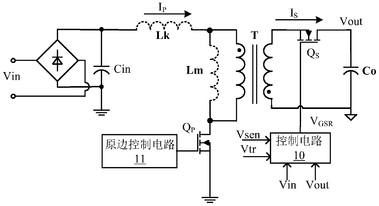
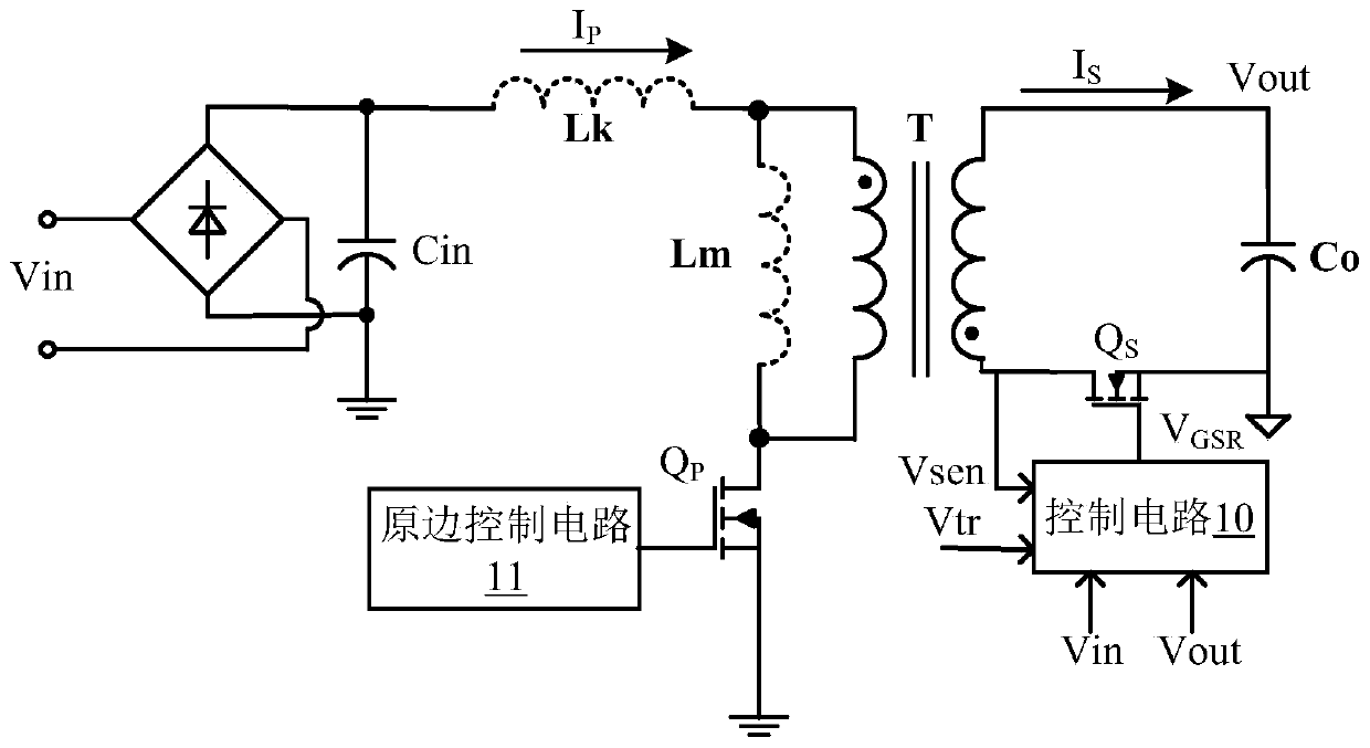
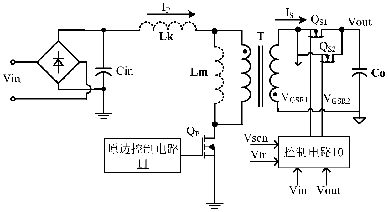
The invention discloses a control circuit and a switching converter using the same. According to a technical scheme in embodiments of the invention, after a main power tube is turned off, a follow current switching tube is controlled to be turned on for a first time period; after the first time period is finished, the follow current switching tube is controlled to be turned on for a second time period within a preset time; therefore, the main power tube realizes parasitic parallel capacitor discharge through a discharge current before being turned on so as to realize zero-voltage conduction and effectively reduce conduction loss; and meanwhile, the follow current switching tube is turned on for a second time period at the resonance valley bottom of the drain-source voltage of the follow current switching tube, so the conduction loss of the follow current switching tube is also reduced, and system efficiency is improved.

Description

technical field [0001] The invention relates to power electronics technology, in particular to a switch converter and its control circuit. Background technique [0002] The switching converter is a power converter that stores energy in the magnetic element when the main power tube is turned on, and delivers the energy stored in the magnetic element to the load when the main power tube is turned off. When the main power tube is turned off, resonance will occur between the magnetic components in the switching converter and the junction capacitance of the main power tube, so conduction loss will occur when the main power tube is turned on again, resulting in low power conversion efficiency. In order to reduce the conduction loss of the main power tube, in the prior art, a quasi-resonance method is used to control the conduction of the main power tube, that is, the main power tube is turned on when the drain-source voltage drops to the lowest point, so as to realize zero-voltage...

Claims


Application Information

Patent Timeline
Patent Type & Authority Applications(China)
IPC IPC(8): H02M3/335
CPCH02M3/33592H02M3/33576H02M3/33561H02M1/0058Y02B70/10H02M1/083
Inventor 邓建金津
Owner SILERGY SEMICON TECH (HANGZHOU) CO LTD
Why Eureka
Try Eureka