
Data latch circuit and pulse signal generator thereof

A pulse signal and generator technology, which is applied in pulse generation, logic circuit pulse generation, electric pulse generation, etc., can solve problems such as misoperation, high area density, data loss, etc., and achieve the effect of correct action

Active Publication Date: 2020-02-14
DIGWISE TECH CORP LTD
View PDF7 Cites 0 Cited by
  • Summary
  • Abstract
  • Description
  • Claims
  • Application Information

AI Technical Summary

Problems solved by technology

In the conventional technical field, although the static flip-flop has a relatively robust effect on the noise margin, it often requires a larger circuit area to be configured, resulting in increased cost
However, the dynamic flip-flops of the conventional technology are prone to data leakage due to the phenomenon of leakage current, and the dynamic flip-flops of the conventional technology also often cause malfunctions due to signal surges.
The design of the pulse latch flip-flop requires a relatively high area density, which is more difficult in circuit layout.

Method used


Image

  • Data latch circuit and pulse signal generator thereof
  • Data latch circuit and pulse signal generator thereof
  • Data latch circuit and pulse signal generator thereof

Examples


Embodiment Construction

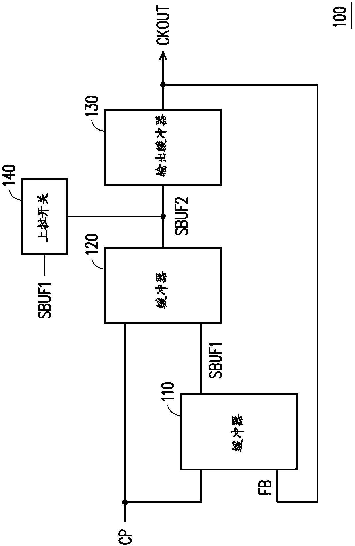
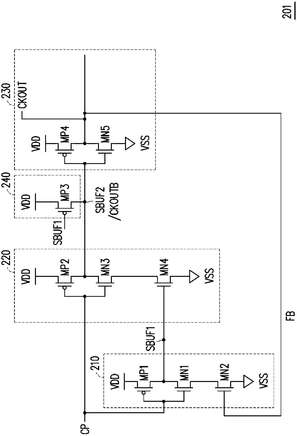
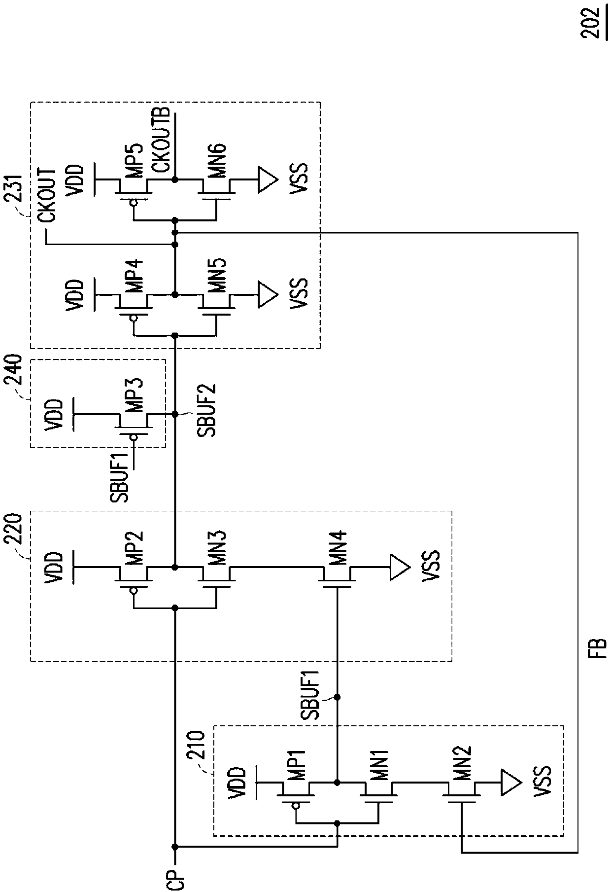
[0028] Please refer to figure 1 , figure 1 A schematic diagram of a pulse signal generator according to an embodiment of the present invention is shown. The pulse signal generator 100 includes buffers 110 , 120 , an output buffer 130 and a pull-up switch 140 . The buffer 110 receives the input signal CP and the feedback signal FB, and generates a buffer signal SBUF1 according to the input signal CP and the feedback signal FB. The buffer 120 is used to receive the input signal CP and the buffer signal SBUF1, and generate the buffer signal SBUF2 according to the input signal CP and the buffer signal SBUF1. The pull-up switch 140 is coupled to the output end of the buffer 120 , receives the buffered signal SBUF1 and pulls up the buffered signal SBUF2 according to the buffered signal SBUF1 . The output buffer 130 is coupled to the buffer 110 and the buffer 120 . The output buffer 130 generates one or more output pulse signals CKOUT according to the buffer signal SBUF2. The ou...


PUM


Abstract

A data latch circuit and a pulse signal generator thereof are provided. The pulse signal generator includes a first buffer, a second buffer, a pull-up switch and an output buffer. The first buffer generates a first buffering signal according to an input signal and a feedback signal. The second buffer generates a second buffering signal according to the input signal and the first buffering signal.The pull-up switch pulls up the second buffering signal according to the first buffering signal. The output buffer generates at least one output pulse signal according to the second buffering signal.The output buffer further outputs the at least one output pulse signal to the first buffer to be the feedback signal.

Description

technical field [0001] The present invention relates to a data latch circuit and its pulse signal generator, and in particular to a fast-acting data latch circuit and its pulse signal generator. Background technique [0002] Regarding the design of the data latch circuit, in the conventional technical field, it is common to use a static flip-flop (static flip-flop), a dynamic flip-flop (dynamic flip-flop) and a pulse latch flipflop (pulse latch flipflop). ) to construct. In the conventional technical field, although the static flip-flop has a relatively robust effect on the noise margin, it usually requires a larger circuit area to be configured, resulting in increased cost. However, the conventional dynamic flip-flops are prone to data leakage due to the phenomenon of leakage current, and the conventional dynamic flip-flops also often cause malfunctions due to signal surges. However, the design of the pulse latch flip-flop requires a relatively high area density, and the ...

Claims


Application Information

Patent Timeline
Patent Type & Authority Applications(China)
IPC IPC(8): H03K19/003H03K19/0175H03K3/017H03K7/08
CPCH03K19/00369H03K19/017545H03K3/017H03K7/08H03K3/012H03K3/35625G11C7/1057H03K3/53G11C7/106H03K3/027
Inventor 吴敬杰杨智文谢文斌
Owner DIGWISE TECH CORP LTD
Learn More