A two-dimensional laser spiral cleaning method

A two-dimensional laser and laser cleaning technology, applied in cleaning methods and appliances, laser welding equipment, chemical instruments and methods, etc., can solve the problems of low cleaning efficiency, slow motor scanning speed, and uneven distribution of ablation area topography

Active Publication Date: 2021-06-29
镇江长悦光电科技有限公司
View PDF5 Cites 0 Cited by
  • Summary
  • Abstract
  • Description
  • Claims
  • Application Information

AI Technical Summary

Problems solved by technology

Based on the laser cleaning application of the galvanometer motor module, the existing scanning mode is line scanning and then line scanning again, which mainly has problems such as poor cleaning uniformity and low cleaning efficiency.
[0003] The poor cleaning uniformity is mainly due to the fact that in the progressive scanning mode of the galvanometer, the laser scans to the line edge area and undergoes a deceleration to reverse acceleration process, while the laser in the non-edge area maintains high-speed deflection
The average speed of laser scanning in the edge area is lower than that in the non-edge area, resulting in a stronger ablation degree in the edge area than in the non-edge area, and uneven distribution of shape height in the ablation area
[0004] The low cleaning efficiency is mainly due to the fact that during the progressive scanning process, the X-axis galvanometer deflects the laser from left to right and then stops deflecting. The Y-axis galvanometer motor starts to deflect the laser to change lines and stop, and then the X-axis galvanometer swings to fill the entire area again and again. During the progressive ablation process, only one axis motor moves at the same time, that is, the laser deflection speed is the speed of the single axis motor, and the slow scanning speed of the motor directly leads to low cleaning efficiency

Method used


Image

  • A two-dimensional laser spiral cleaning method
  • A two-dimensional laser spiral cleaning method
  • A two-dimensional laser spiral cleaning method

Examples


Embodiment Construction

[0034] In order to better understand the present invention, the content of the present invention is further illustrated below in conjunction with the examples, but the content of the present invention is not limited to the following examples.

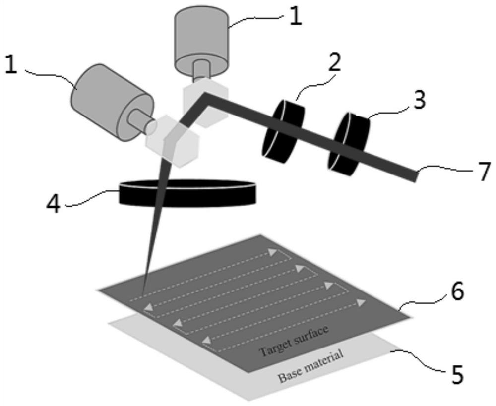
[0035] Such as figure 1 As shown, the fiber laser with a wavelength of 1064nm passes through the optical isolation system and the collimation system, and then enters the mirror on the motor shaft of the digital galvanometer. Surface stains on. figure 1 The target surface is shown for the existing row scan path.

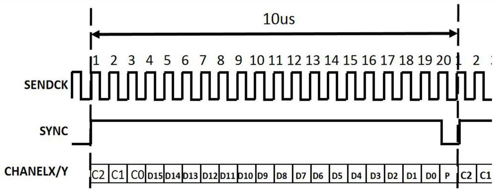
[0036] The cleaning system sends instructions representing the deflection angle of the motor to the digital galvanometer motor interface through the XY2-100 protocol to control the rotation of the motor. Such as figure 2 As shown, the protocol stipulates that the command data length is 20 bits, and the structure is 3 control bits, 16 data bits, 1 even parity bit, and the 16-bit data bit linearly corresponds to the absolute ...


PUM


Abstract

The invention discloses a two-dimensional laser spiral cleaning method. The laser cleaning system includes two orthogonally deflected digital vibrating mirror motors. On the mirror on the shaft of the digital galvanometer motor, after secondary reflection, the field lens is constrained to focus on the surface stains on the ablation target substrate in a two-dimensional plane; the interface protocol of the two digital galvanometer motors is XY2‑ 100; The two digital vibrating mirror motors are independently controlled. The two-dimensional laser spiral cleaning method of the present invention, for any point in the cleaning area, compared with line-by-line ablation, the laser returns to the vicinity of the point after completing the outer ring according to the spiral filling path, and the point area obtains cooling time, The heat accumulation effect of the laser is weakened; the progressive scanning speed is the speed of a single vibrating mirror motor, and the helical scanning speed is the vector sum of the two motor speeds. Therefore, compared with the progressive scanning method, the laser spiral cleaning effect is more uniform and the cleaning efficiency is higher. high.

Description

technical field [0001] The invention relates to a two-dimensional laser spiral cleaning method, which belongs to the field of two-dimensional laser cleaning. Background technique [0002] Two-dimensional laser cleaning means that the laser scans on a two-dimensional plane through the deflection of the galvanometer motor, and ablates the oil, rust or oxide layer on the surface of the target, so as to achieve the effect of cleaning the surface of the target. Based on the laser cleaning application of the galvanometer motor module, the existing scanning mode is line scanning and then line scanning again, which mainly has problems such as poor cleaning uniformity and low cleaning efficiency. [0003] The poor cleaning uniformity is mainly due to the fact that in the progressive scanning mode of the galvanometer, the laser scans to the line edge area and undergoes a deceleration to reverse acceleration process, while the laser in the non-edge area maintains high-speed deflection....

Claims


Application Information

Patent Timeline
Patent Type & Authority Patents(China)
IPC IPC(8): B08B7/00B23K26/362
CPCB08B7/0042B23K26/362
Inventor 汤发全
Owner 镇江长悦光电科技有限公司
Why Eureka
Try Eureka