
Mechanical locking mechanism and electromechanical interlocking suspending cage

A technology of mechanical locking and hanging cages, which is applied to elevators, transportation, and packaging in buildings. It can solve problems such as low operating efficiency that cannot guarantee construction, easily deformed floor openings, and no quality assurance for materials. It achieves a simple structure. , The self-locking state is stable and the effect of avoiding potential safety hazards

Inactive Publication Date: 2020-02-18
广州市第三建筑工程有限公司
View PDF13 Cites 0 Cited by
  • Summary
  • Abstract
  • Description
  • Claims
  • Application Information

AI Technical Summary

Problems solved by technology

Therefore, the low operating efficiency cannot guarantee the construction, and because the mechanical lock is located in the direction of the construction elevator and outside the floor, the wind and sun all year round will greatly damage the mechanical lock and it is not conducive to maintenance
The landing doors of construction elevators are made of on-site materials. The manufacturing method is simple, and the materials have no quality assurance. They are easily deformed and cannot seal the floor openings tightly, resulting in safety accidents such as falling objects from heights.

Method used


Image

  • Mechanical locking mechanism and electromechanical interlocking suspending cage
  • Mechanical locking mechanism and electromechanical interlocking suspending cage
  • Mechanical locking mechanism and electromechanical interlocking suspending cage

Examples


Embodiment Construction

[0026] In the description of the present invention, it should be understood that the orientation descriptions, such as up, down, front, back, left, right, etc. indicated orientations or positional relationships are based on the orientations or positional relationships shown in the accompanying drawings, only It is for the convenience of describing the invention and simplifying the description, rather than indicating or implying that the device or element referred to must have a specific orientation, be constructed and operated in a specific orientation, and thus should not be construed as a limitation of the invention.

[0027] In the description of the present invention, several means one or more, and multiple means two or more. Greater than, less than, exceeding, etc. are understood as not including the original number, and above, below, within, etc. are understood as including the original number. If the description of the first and second is only for the purpose of distingu...


PUM


Abstract

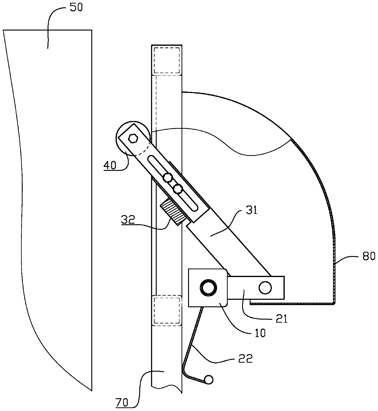
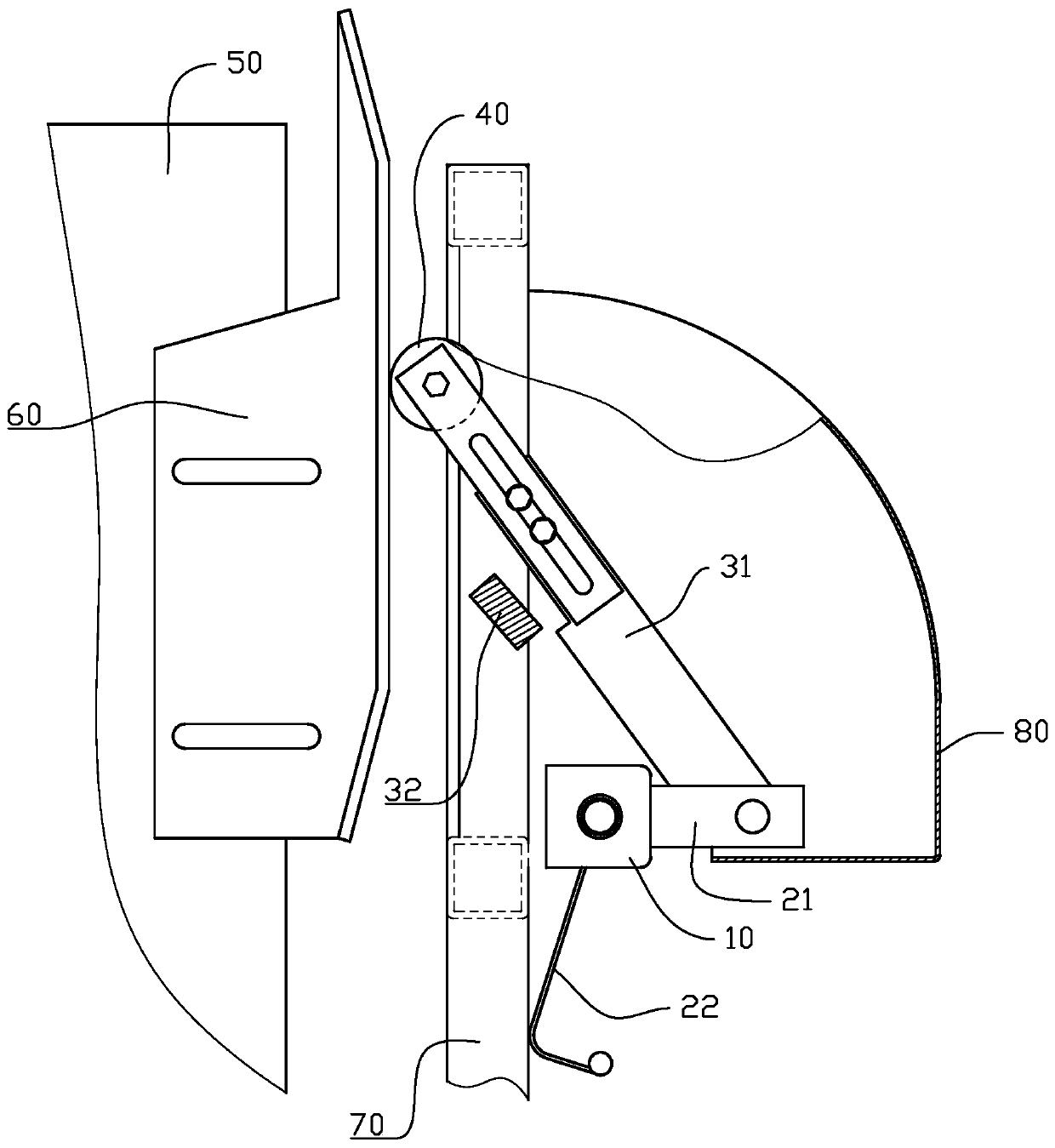
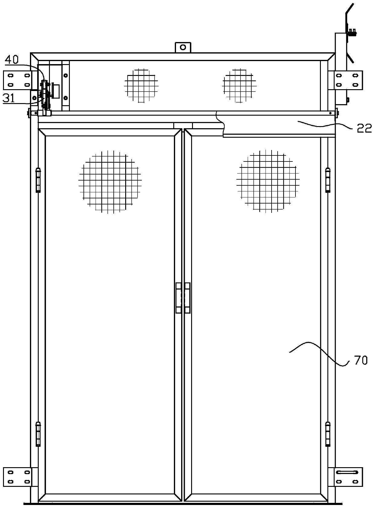
The invention discloses a mechanical locking mechanism and an electromechanical interlocking suspending cage. The mechanical locking mechanism comprises a base, a baffle block, a collision block, a transmission arm, a thrust arm and a roller, wherein the roller is hinged and fixed to the upper end of the thrust arm; the transmission arm is hinged with the lower end of the thrust arm; under an initial state, the step position of the thrust arm is in lap joint on the baffle block, and cannot move upwards; after the roller is in contact with the collision block, the roller drives the thrust arm to upwards lift by a few distance in an inclined mode, so that the transmission arm can freely push the thrust arm to move only after the thrust arm is separated from the baffle block; the electromechanical interlocking suspending cage applies the mechanism, and is matched with an electrical control system, so that a power supply or a motor is cut off while a door plate is opened, and therefore, the suspending cage cannot lift. According to the whole scheme, the mechanical locking mechanism is high in safety, is convenient in modification, and is used for the field of building construction lifters.

Description

technical field [0001] The invention relates to the field of building construction elevators, in particular to a mechanical locking mechanism and an electromechanical interlocking cage. Background technique [0002] Construction elevators (also called cages) are important vertical transportation equipment in the construction of high-rise buildings and super high-rise buildings. Because construction elevators are mixed with passengers and goods, they operate in the open air, the working environment is harsh, and there are many uncertain factors. Therefore, construction elevators are also one of the major sources of danger on the construction site. In order to ensure the safety of the construction elevator, the floor protective door for the construction elevator is an important safety guarantee measure for the construction elevator, and it is an important condition for the safe and efficient operation of the construction elevator in daily use. [0003] The floor doors of the ...

Claims


Application Information

Patent Timeline
Patent Type & Authority Applications(China)
IPC IPC(8): B66B13/20
CPCB66B13/20
Inventor 唐开永周岳峰杜向浩李志文曾志斌邹启明陈祥波
Owner 广州市第三建筑工程有限公司
Learn More