Supercharge Your Innovation With Domain-Expert AI Agents!

Furnace temperature monitoring system and method

A monitoring system and furnace temperature technology, applied in thermometers, thermometers and instruments using electrical/magnetic components directly sensitive to heat, etc., can solve the impact of product quality, thermocouples not working properly, and uneven temperature of wave soldering devices, etc. problems, to achieve the effect of timely judgment

Inactive Publication Date: 2020-02-18
INVENTEC PUDONG TECH CORPOARTION +1
View PDF5 Cites 0 Cited by
  • Summary
  • Abstract
  • Description
  • Claims
  • Application Information

AI Technical Summary

Problems solved by technology

Due to the long-term operation of the thermocouple, there is a problem of aging or disconnection, which leads to uneven, high, and low temperature in the furnace of the wave soldering device, which makes the heating effect poor or causes poor tin eating, cold soldering, etc. in electronic products. Phenomena such as empty soldering, deformation, tin bridge, tin wire, etc.
In addition, each temperature zone in the wave soldering device is equipped with multiple thermocouples. When one of the thermocouples fails, other thermocouples in the same temperature zone may perform thermal compensation to ensure that the overall furnace temperature is stable or not perform thermal compensation. As a result, the furnace temperature is unstable. Therefore, the traditional furnace temperature monitoring cannot accurately and timely judge whether there is a situation where the thermocouple is not working properly. Only when the temperature exceeds the set threshold will a warning signal be generated, and the engineer will see the warning signal. Going to process, but the quality of the product in the furnace has been severely affected
[0004] To sum up, it can be seen that there has been a problem in the existing technology for a long time that it is impossible to accurately and timely judge whether there is a thermocouple that is not working properly. Therefore, it is necessary to propose improved technical means to solve this problem

Method used

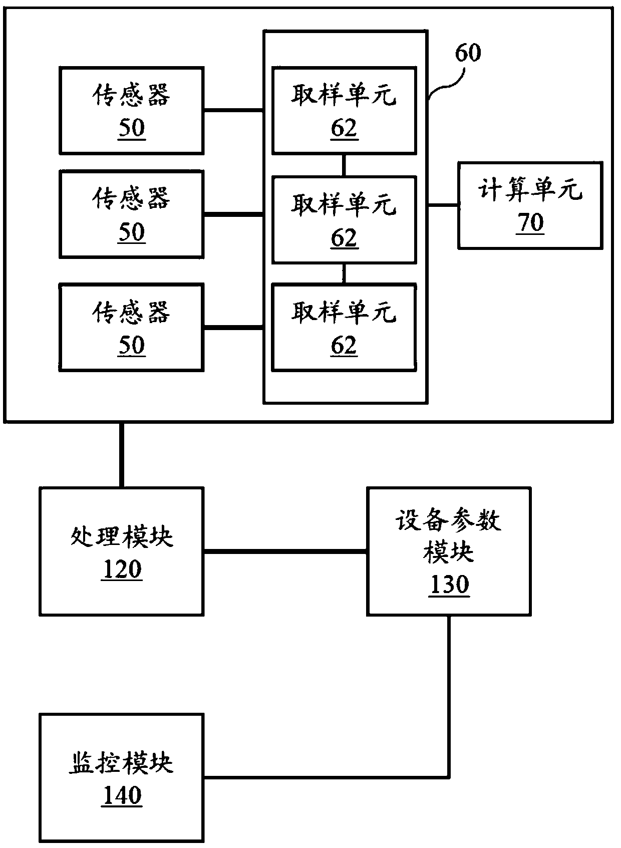
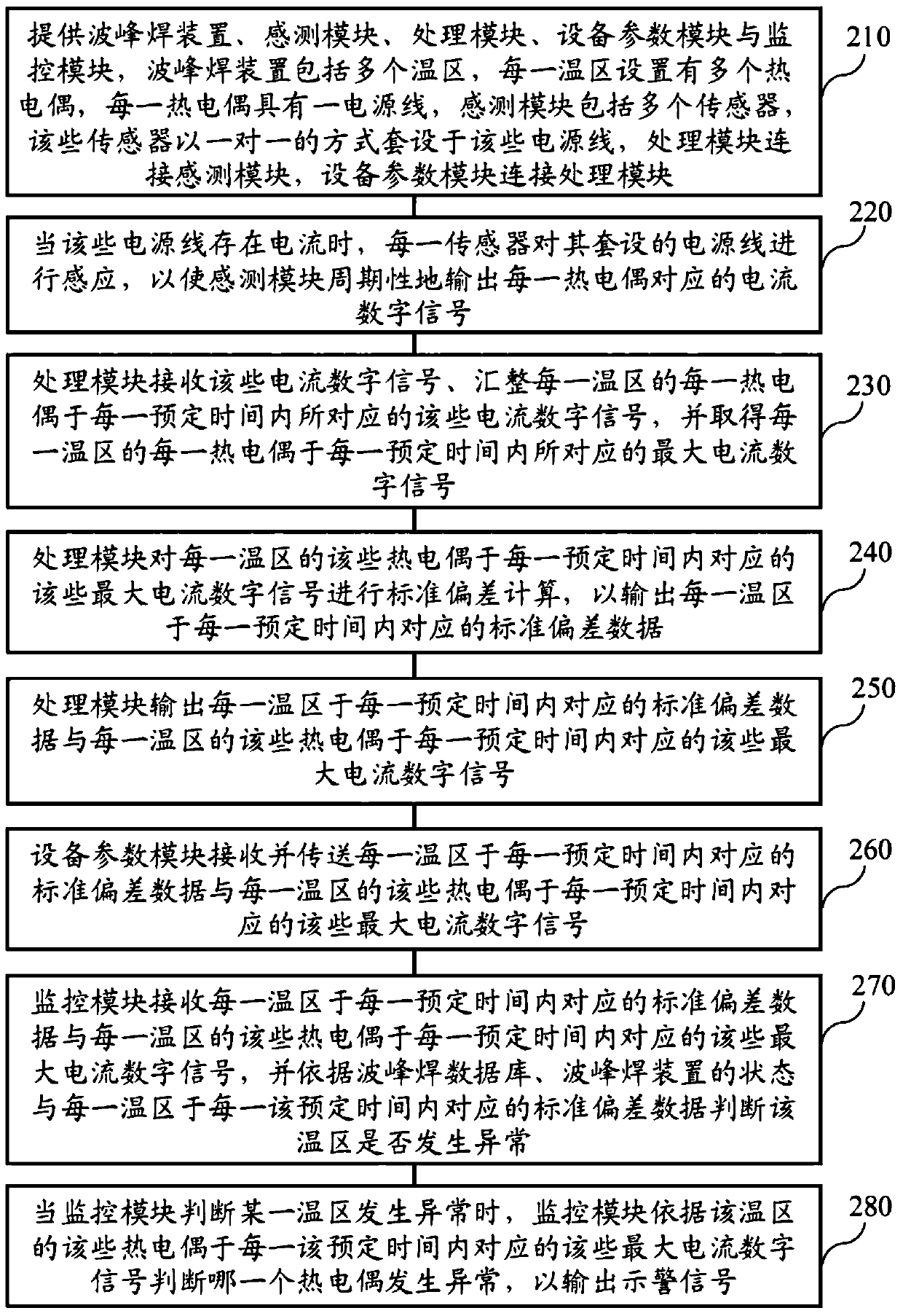

Image

  • Furnace temperature monitoring system and method
  • Furnace temperature monitoring system and method

Examples


Embodiment Construction

[0030] Before describing the furnace temperature monitoring system and method thereof disclosed in the present invention, the nouns defined in the present invention will be described first. The modules and units included in the furnace temperature monitoring system of the present invention can be realized in various ways. Includes software, hardware, firmware or any combination thereof. The technology presented in the implementation uses software or firmware that can be stored on a machine-readable storage medium, such as: read only memory (ROM), random access memory (RAM), magnetic disk storage medium, optical storage medium, flash memory device, etc. , and can be executed by one or more general or special purpose programmable microprocessors.

[0031] The implementation of the present invention will be described in detail below with reference to the drawings and examples, so as to fully understand and implement the implementation process of how to use technical means to solv...


PUM


Abstract

The invention provides a furnace temperature monitoring system, which is characterized in that: each sensor is used for sensing a sleeved power line so as to enable a sensing module to periodically output a corresponding current digital signal; a processing module is used for obtaining a maximum current digital signal corresponding to each thermocouple of each temperature zone in each preset time,and performing standard deviation calculation to output standard deviation data; a monitoring module is used for judging whether the temperature zone is abnormal or not according to a wave-solderingdatabase, a state of a wave-soldering device and the corresponding standard deviation data of each temperature zone in each preset time; and when a certain temperature zone is judged to be abnormal, the monitoring module is used for judging which thermocouple is abnormal according to the maximum current digital signals corresponding to the thermocouples in each preset time in the temperature zoneso as to output a warning signal, thereby accurately and timely judging whether there is a thermocouple which cannot work normally or not.

Description

technical field [0001] The invention relates to a monitoring system and method thereof, in particular to a furnace temperature monitoring system and method thereof. Background technique [0002] At present, in the production of electronic products, wave soldering technology is more and more widely used. In order to ensure the stability of wave soldering quality, it is necessary to monitor the temperature of wave soldering furnace to ensure the quality of wave soldering and meet product requirements. [0003] Generally speaking, traditional furnace temperature monitoring relies on thermocouples and temperature displays to measure and read the temperature. First, the thermocouple is heated to convert the thermal potential difference into a potential difference, and then the potential difference is converted to the corresponding temperature. Due to the long-term operation of the thermocouple, there is a problem of aging or disconnection, which leads to uneven, high, and low tem...

Claims


Application Information

Patent Timeline
Patent Type & Authority Applications(China)
IPC IPC(8): G01K7/02
CPCG01K7/02
Inventor 朱令
Owner INVENTEC PUDONG TECH CORPOARTION
Features
  • R&D
  • Intellectual Property
  • Life Sciences
  • Materials
  • Tech Scout
  • Unparalleled Data Quality
  • Higher Quality Content
  • 60% Fewer Hallucinations
Learn More