Low frequency oscillator of multi-frequency antenna

A low-frequency oscillator and multi-frequency antenna technology, applied in the field of antennas, can solve the problems of high-frequency performance, high-frequency pattern distortion, and difficult design of low-frequency oscillators, and achieve the effect of low production cost.

Active Publication Date: 2020-02-18
FOSHAN CITY EAHISON COMM
View PDF4 Cites 0 Cited by
  • Summary
  • Abstract
  • Description
  • Claims
  • Application Information

AI Technical Summary

Problems solved by technology

Ordinary low-frequency radiation units have an impact on the performance of high-frequency, causing distortion of the high-frequency pattern and affecting the performance of mobile communication networks
In order to solve this problem, many low-frequency vibrators with different structures are currently used, but these low-frequency vibrators are generally difficult to design, and they still have problems such as affecting the high-frequency pattern when used.

Method used


Image

  • Low frequency oscillator of multi-frequency antenna
  • Low frequency oscillator of multi-frequency antenna
  • Low frequency oscillator of multi-frequency antenna

Examples


Embodiment 1

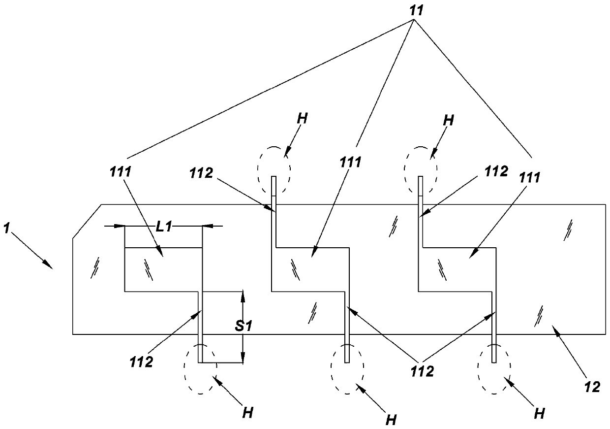
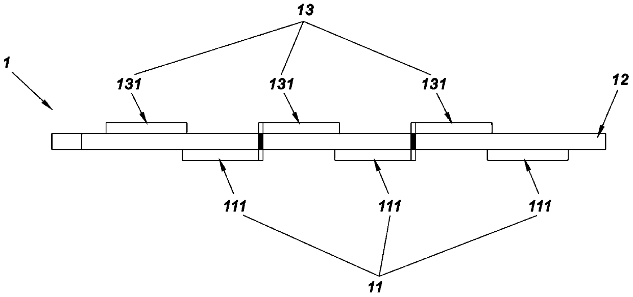
[0027] Such as Figure 1 to Figure 4 As shown, the low-frequency vibrator 1 of a multi-frequency antenna in this embodiment includes: an upper conductor layer 11 , an intermediate dielectric layer 12 and a lower conductor layer 13 . Wherein, the upper conductor layer 11 and the lower conductor layer 13 are stamped from aluminum plate, the intermediate dielectric layer 12 is made of non-conductive plastic, and the intermediate dielectric layer 12 is located between the upper conductor layer 11 and the lower conductor layer 13 .

[0028] Such as figure 1 As shown, the upper conductor layer 11 includes three upper vibrator segments 111 , all of which are planar thin slices, and the three upper vibrator segments 111 are separated from each other and arranged in a straight line.

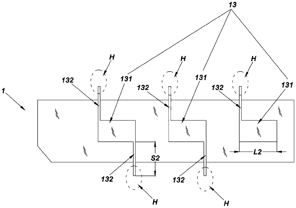
[0029] Such as figure 2 As shown, the lower conductor layer 13 includes three lower vibrator segments 131 made of metal. The three lower vibrator segments 131 are all planar thin slices, and the three ...

Embodiment 2

[0036] Such as Image 6 , Figure 7 As shown, the low-frequency vibrator 5 of a multi-frequency antenna in this embodiment includes: an upper conductor layer 51 , an intermediate dielectric layer 52 and a lower conductor layer 53 . One copper-clad surface of the double-sided PCB is used to make the upper conductor layer 51 , the other copper-clad surface is used to make the lower conductor layer 53 , and the middle insulating layer of the double-sided PCB is used as the middle dielectric layer 52 . The end of the upper conductor of the short-circuit branch and the end of the lower conductor of the short-circuit branch adopt a metallized hole process to realize conduction.

[0037] Such as Image 6 As shown, the upper conductor layer 51 includes two upper vibrator segments 511 , both of which are planar copper clad areas, and the two upper vibrator segments 511 are separated from each other and arranged in a straight line.

[0038] Such as Figure 7 As shown, the lower cond...


PUM


Abstract

The invention aims to provide a low frequency oscillator with a simple structure, small volume and little influence on a high frequency pattern. The low frequency oscillator comprises an upper conductor layer, an intermediate dielectric layer and a lower conductor layer. The upper conductor layer comprises 2-5 pieces of upper oscillator segments made of metal, and the upper oscillator segments arearranged in a straight line and separated from each other. The lower conductor layer comprises 2-5 lower oscillator segments made of metal, and the lower oscillator segments are arranged in a straight line and separated from each other. The projections of the straight line arranged by the upper oscillator segments and the straight line arranged by the lower oscillator segments on the plane wherethe intermediate medium layer is located coincide, and the projections of the upper oscillator segments and the lower oscillator segments on the plane where the intermediate medium layer is located are mutually staggered. The upper oscillator segments are provided with short circuit branch upper conductors, and the lower vibrator segments are provided with short circuit branch lower conductors. The upper oscillator segments and the lower oscillator segments are conducted hand in hand through the short circuit branch upper conductors and the short circuit branch lower conductors. The manufacturing cost of the low frequency oscillator is relatively low, and the low frequency oscillator has little influence on the high frequency pattern and S parameters.

Description

technical field [0001] The invention relates to the technical field of antennas, in particular to a low-frequency vibrator for a multi-frequency antenna. Background technique [0002] A low-frequency radiation unit and a high-frequency radiation unit are included in a mobile communication multi-frequency antenna at the same time. Ordinary low-frequency radiation units have an impact on high-frequency performance, causing distortion in the high-frequency pattern and affecting the performance of mobile communication networks. In order to solve this problem, many low-frequency vibrators with different structures are used at present, but these low-frequency vibrators are generally difficult to design, and they still affect the high-frequency pattern when used. [0003] Therefore, it is necessary to further improve the structure of the existing low-frequency vibrator used for multi-frequency antennas. Contents of the invention [0004] The object of the present invention is t...

Claims


Application Information

Patent Timeline
IPC IPC(8): H01Q1/38H01Q1/50
CPCH01Q1/38H01Q1/50
Inventor 尚春辉郑洪振孙耀志刘灼鹏钱伟雄
Owner FOSHAN CITY EAHISON COMM
Why Eureka
Try Eureka