
Waste automobile shell shredding recovery equipment

A technology of automobile casing and recycling equipment, which is applied in the field of equipment that splits materials into pieces by tearing parts, can solve the problems of low production efficiency, and achieve the effects of small processing resistance, uniform output size, and high shredding efficiency

Pending Publication Date: 2020-02-21
YUNNAN TAIBIAO NUMERICAL CONTROL MACHINE CO LTD
View PDF0 Cites 1 Cited by
  • Summary
  • Abstract
  • Description
  • Claims
  • Application Information

AI Technical Summary

Problems solved by technology

At present, excavators, punchers, cutters and road rollers are mainly used for processing and crushing, and the production efficiency is low

Method used


Image

  • Waste automobile shell shredding recovery equipment
  • Waste automobile shell shredding recovery equipment
  • Waste automobile shell shredding recovery equipment

Examples


Embodiment 1

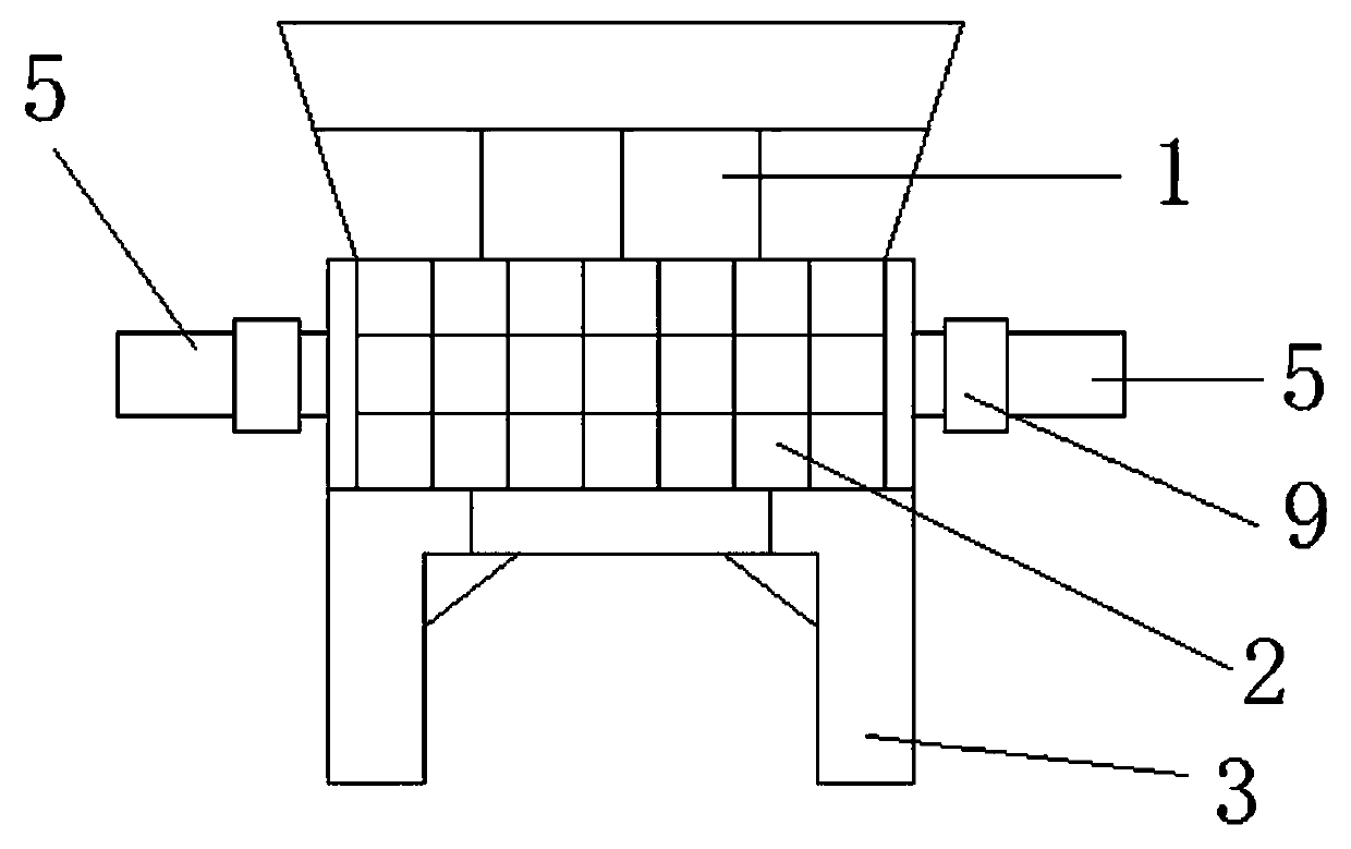
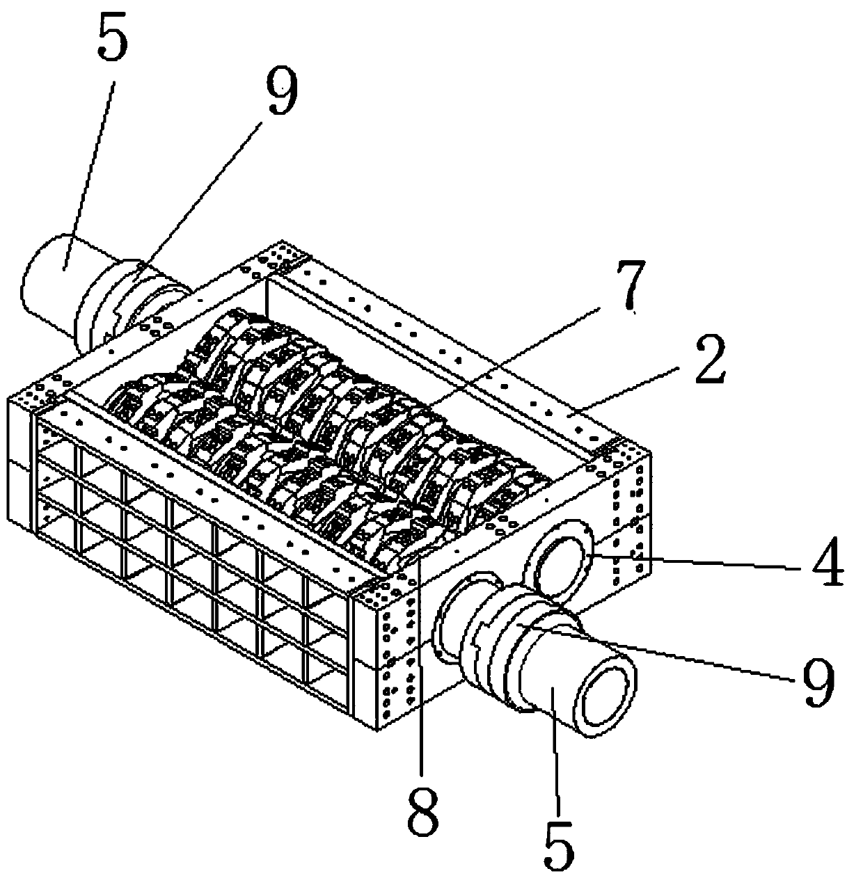
[0019] Embodiment 1: as figure 1 -shown in -6, a kind of waste automobile casing shreds recovery equipment, comprises drop hopper 1, crushing box 2, frame 3 and conveying line, described frame 3 top is provided with crushing box 2, and the top of crushing box 2 is provided with A conveying line is arranged below the falling hopper 1 and the crushing box 2, and two cutter shafts 5 arranged in parallel and rotating in opposite directions are arranged horizontally through bearings 4 in the crushing box 2.

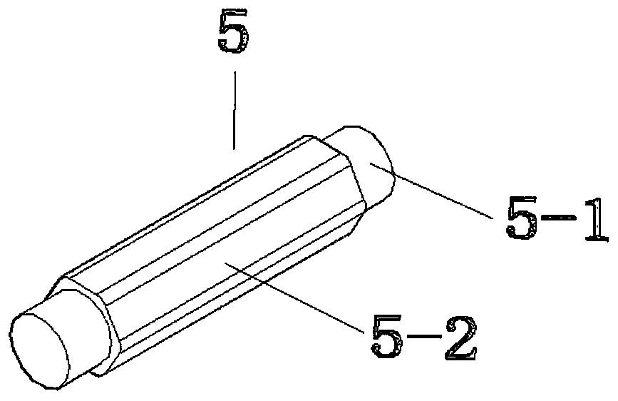
[0020] The cutter shaft 5 is provided with a bearing installation section 5-1 and a blade installation section 5-2, the section of the blade installation section 5-2 is a regular hexagon, and the axial direction of the cutter shaft 5 is arranged with first knives Body 11, the second cutter body 12, the third cutter body 13 and the fourth cutter body 14, spacer ring 7 for isolation is installed between adjacent two cutter bodies, the installation width of cutter body and spacer...

Embodiment 2

[0023] Embodiment 2: as figure 1 -shown in -6, a kind of waste automobile casing shreds recovery equipment, comprises drop hopper 1, crushing box 2, frame 3 and conveying line, described frame 3 top is provided with crushing box 2, and the top of crushing box 2 is provided with A conveying line is arranged below the falling hopper 1 and the crushing box 2, and two cutter shafts 5 arranged in parallel and rotating in opposite directions are arranged horizontally through bearings 4 in the crushing box 2.

[0024] The cutter shaft 5 is provided with a bearing installation section 5-1 and a blade installation section 5-2, the section of the blade installation section 5-2 is a regular hexagon, and the axial direction of the cutter shaft 5 is arranged with first knives Body 11, the second cutter body 12, the third cutter body 13 and the fourth cutter body 14, spacer ring 7 for isolation is installed between adjacent two cutter bodies, the installation width of cutter body and spacer...


PUM


Abstract

The invention discloses waste automobile shell shredding recovery equipment comprising a falling hopper (1), a smashing box (2), a rack (3) and a conveying line. The smashing box (2) is arranged abovethe rack (3). The falling hopper (1) is arranged above the smashing box (2). The conveying line is arranged below the smashing box (2). Two cutter shafts (5) are horizontally arranged in the smashingbox (2) in parallel through bearings (4) and rotate oppositely. Locating of the circumferential phase position is achieved between cutter bodies and the cutter shafts (5) in a hole shaft sleeved mode. A 15-degee included angle exists between axes of the cutter bodies, thus all the cutter bodies are installed behind the cutter shafts (5) sequentially in a sleeving mode, the connection line of blades (10-2) is a spiral line, through the specific cutter body structure, the effect that the blades on all the cutter bodies are distributed in a spiral line shape in the axial direction of the cuttershafts is ensured, in this way, in the machining process of a cutter set, different blades in the cutter set do not participate in shredding machining simultaneously, machining resistance is low, power consumption is low, shredding efficiency is high, and discharge sizes are uniform.

Description

technical field [0001] The invention relates to a device for splitting materials into fragments by using tearing parts, in particular to a device for shredding and recycling waste automobile casings. Background technique [0002] The automobile manufacturing industry has become a pillar industry in my country, and it is also a large resource consumer. With the development of the economy, more and more scrapped cars are being scrapped. Therefore, it is very important to effectively recycle and reuse waste car shells. Before recycling, car shells Must be dealt with. Existing methods mainly rely on excavators, punchers, cutters and road rollers for processing and crushing, and the production efficiency is low. Contents of the invention [0003] In order to solve the above problems, the present invention provides a waste automobile casing shredding and recycling device with high working efficiency, safety and reliability, and uniform discharge size. [0004] In order to achie...

Claims


Application Information

Patent Timeline
Patent Type & Authority Applications(China)
IPC IPC(8): B02C18/18B02C18/14B02C18/24B09B3/00
CPCB02C18/182B02C18/14B02C18/24B09B3/00B02C2201/06B02C18/0084
Inventor 张永林张杰查云伟杨立武陈国峰杜杰陈家美张永伟白云珠可存江吴金灿
Owner YUNNAN TAIBIAO NUMERICAL CONTROL MACHINE CO LTD
Learn More