Paint spraying device for production of network filters

A network filter and paint technology, applied in the direction of spraying devices, liquid spraying devices, etc., can solve the problems that the distance between the paint spraying head and the equipment to be painted cannot be adjusted, and affect the painting process of the equipment, so as to achieve convenient painting treatment, convenient use, and guaranteed painting quality effect

Inactive Publication Date: 2020-02-21
LEIYANG YAXIANG ELECTRONICS TECH
View PDF7 Cites 3 Cited by
  • Summary
  • Abstract
  • Description
  • Claims
  • Application Information

AI Technical Summary

Problems solved by technology

[0003] The currently published Chinese patent authorization announcement number is CN209476561U, a kind of mechanical parts painting device. Although it can be painted, the equipment cannot adjust the distance between the painting head and the equipment to be painted, thus affecting the equipment to carry out the painting process.

Method used


Image

  • Paint spraying device for production of network filters
  • Paint spraying device for production of network filters
  • Paint spraying device for production of network filters

Examples


Embodiment 1

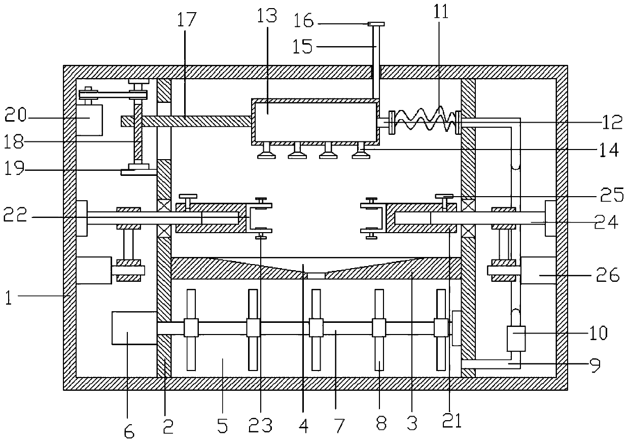
[0025] refer to Figure 1~3 , in an embodiment of the present invention, a painting device for network filter production, including a support frame 1, the left and right ends of the support frame 1 are provided with first partitions 2, and the lower end between the first partitions 2 is provided with a second The partition 3 can divide the support frame 1 into several areas, so as to facilitate the installation of the equipment and the wiring of the equipment, so as to ensure the beauty of the equipment structure and facilitate people's maintenance and treatment. The middle part of the second partition 3 is provided with a drain tank 4. A paint storage chamber 5 is provided on the lower side of the second partition 3, and the drain tank 4 on the second partition 3 can not only facilitate the addition of paint to the inside of the paint storage chamber 5, but also facilitate the redundant waste of the equipment during the painting process. The paint re-enters the interior of th...

Embodiment 2

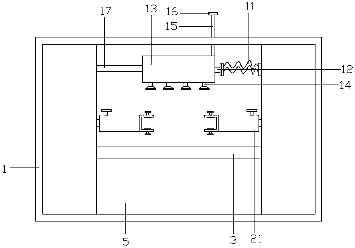
[0029] The difference from Embodiment 1 is that the upper right end of the connection chamber 13 is provided with a limit rod 15, the limit rod 15 passes through the support frame 1, and a limit block 16 is installed on the limit rod 15 on the upper side of the support frame 1, which can effectively The connection cavity 13 is limited, so that the stability of the connection cavity 13 can be ensured.


PUM


Abstract

The invention relates to the field of production and machining of network filters, in particular to a paint spraying device for production of the network filters. The device comprises a supporting frame. First partitions are arranged at the left end and the right end of the supporting frame, a second partition is arranged at the lower end of the portion between the first partitions, a paint storage cavity is formed in the lower side of the second partition, a liquid suction pump is arranged on the right side of the paint storage cavity, the upper side of the liquid suction pipe is connected with a connecting hose through a connecting flange, the connecting hose is connected with a liquid adding pipe through a connecting flange, the liquid adding pipe is mounted on the right side of a connecting cavity, nozzles are arranged on the lower side of the connecting cavity, a connecting plate is arranged on the left side of the connecting cavity, a threaded rod is arranged on the portion, on the left side of the first partition located at the left end, of the connecting plate, the middles of the first partitions are connected with connecting rods through bearings, the portions, located onthe inner sides of the first partitions, of the connecting rods are connected with connecting pipes through fastening rotary knobs, and clamping grooves are fixedly mounted in the inner sides of the connecting pipes. Paint can be effectively and conveniently sprayed to the network filters, and the equipment is convenient to use.

Description

technical field [0001] The invention relates to the field of network filter production and processing, in particular to a painting device for network filter production. Background technique [0002] The function of the filter is to allow the signal of a certain part of the frequency to pass smoothly, while the signal of the other part of the frequency is greatly suppressed. It is essentially a frequency selection circuit. In the filter, the frequency range in which the signal can pass is called the passband or passband; conversely, the frequency range in which the signal is greatly attenuated or completely suppressed is called the stopband; the boundary frequency between the passband and the stopband is called is the cut-off frequency; the voltage gain of the ideal filter is constant in the passband, and the voltage gain in the stopband is zero; there is a transition band of a certain frequency range between the passband and stopband of the actual filter, and the filter is i...

Claims


Application Information

Patent Timeline
Patent Type & Authority Applications(China)
IPC IPC(8): B05B9/04B05B12/12B05B13/02B05B15/25
CPCB05B9/0403B05B12/124B05B13/0228B05B15/25
Inventor 陈小勇朱千林杨艳军
Owner LEIYANG YAXIANG ELECTRONICS TECH
Why Eureka
Try Eureka