High-speed foot cutting die for LED lead frame

A lead frame, high-speed technology, applied in the field of LED lead frame high-speed cutting dies, can solve the problems of unstable stamping production quality, no oil supply, and high quality requirements for LED lead frames.

Active Publication Date: 2020-02-21
吉安市木林森精密科技有限公司
View PDF7 Cites 0 Cited by
  • Summary
  • Abstract
  • Description
  • Claims
  • Application Information

AI Technical Summary

Problems solved by technology

In recent years, the development of lead frame technology has advanced by leaps and bounds. The development of lead frame specifications has become smaller and smaller, the arrangement has become tighter, the width of the sheet has become larger and the thickness of the material has become thinner and thinner. Major manufacturers are vying to follow suit. The price of lamp beads It has been continuously explored, but there is basically no breakthrough in material selection; LED hardware lead frame technology has been developed so far, and its materials are still red copper, brass, and iron. After researching the market metal strips, it seems difficult to find a fourth. cost-effective material
[0005] After research, it was found that the performance of the aluminum lead frame was not worse than that of the copper lead frame, and even slightly better than that of the copper lead frame; this means that the aluminum lead frame has a relatively Copper lead frame ha...

Method used


Image

  • High-speed foot cutting die for LED lead frame
  • High-speed foot cutting die for LED lead frame
  • High-speed foot cutting die for LED lead frame

Examples


Embodiment Construction

[0037] The present application will be described in further detail below through specific embodiments in conjunction with the accompanying drawings.

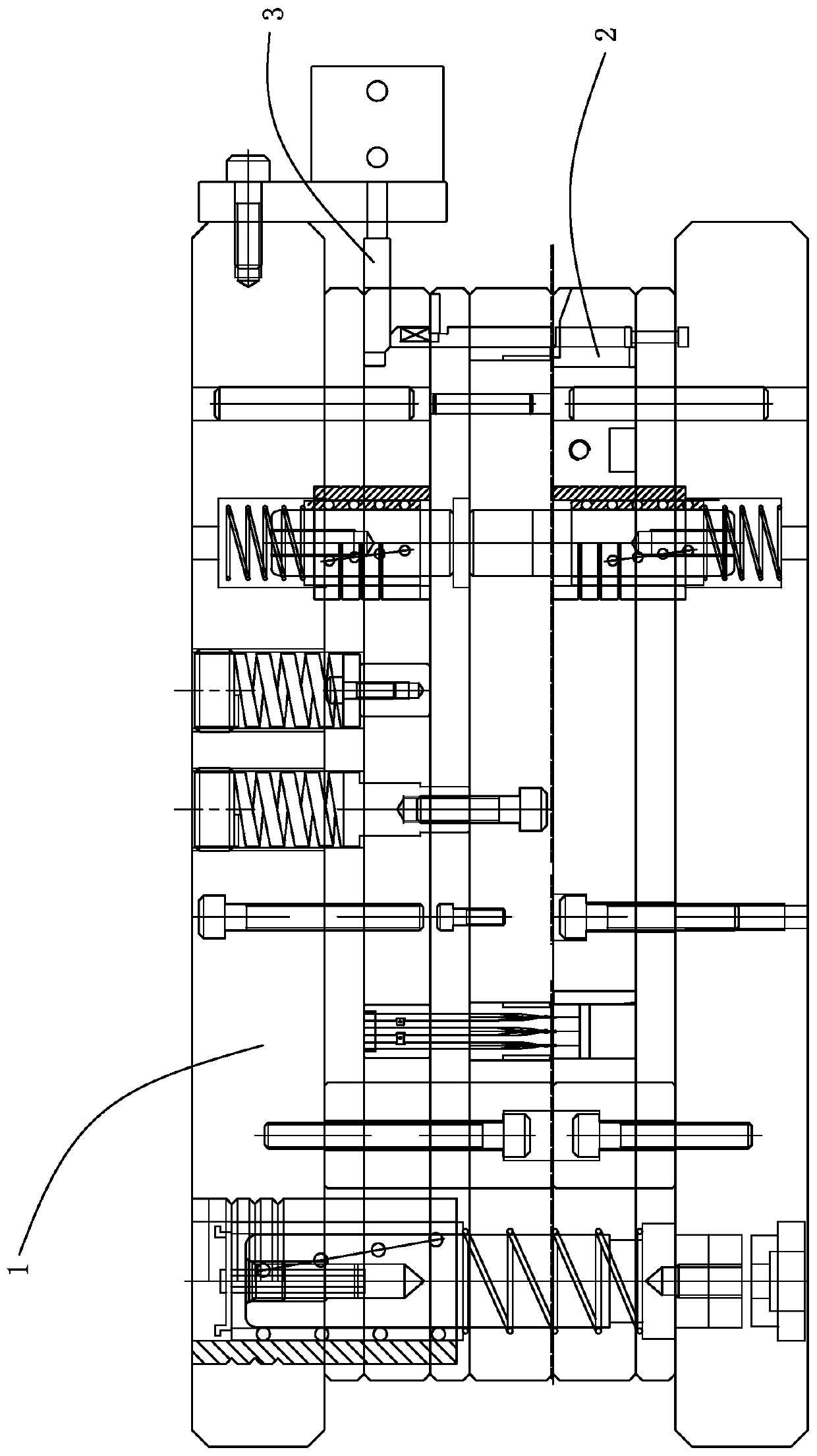
[0038] Such as Figure 1-15 As shown, the LED lead frame high-speed foot cutting die includes an upper die set 1 and a lower die set 2 adapted to the upper die set 1 .

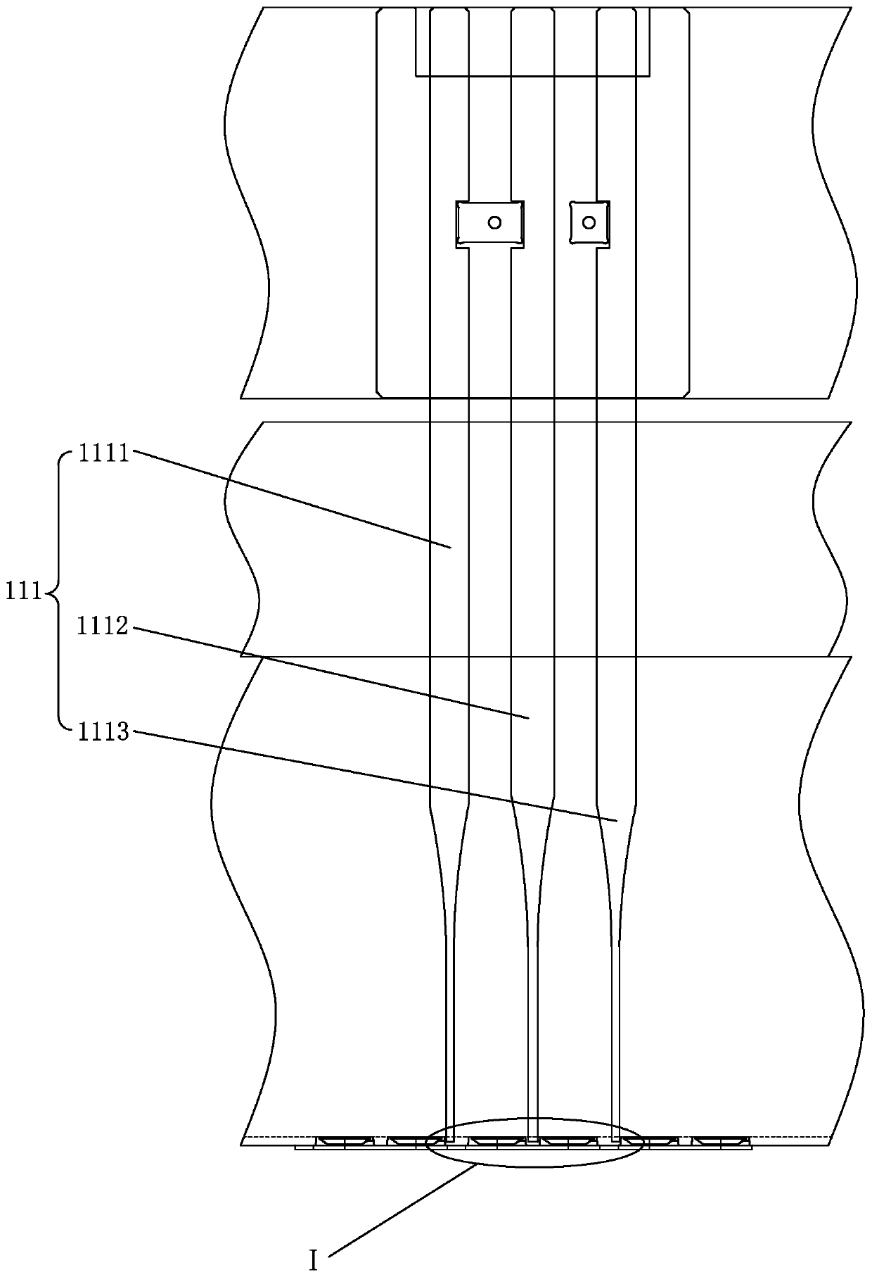
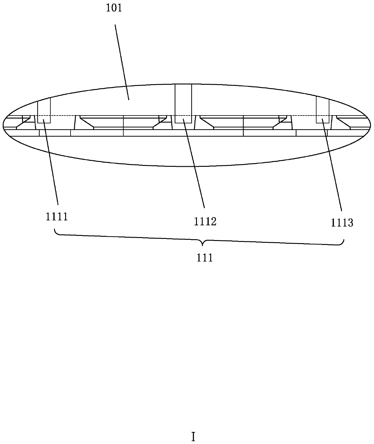
[0039]Specifically, the upper die set 1 is provided with a first punch group 11 and a second punch group 12 located on one side of the first punch group 11, and the first punch group 11 includes at least one set of the first punch group 12. A punch group 111, the second punch group 12 includes at least one set of second punch groups 121, the first punch group 111 and the second punch group 121 are along the longitudinal direction of the upper die group 1 The directions are staggered, and the punching ends of the first punch group 111 and the second punch group 121 protrude from the lower side of the upper die group 1;

[0040] The lower die group 2 is provided...


PUM


Abstract

The invention discloses a high-speed foot cutting die for an LED lead frame. The high-speed foot cutting die includes an upper module and a lower module. The upper module is provided with a first punch group and a second punch group. The first punch group includes at least one first punch set, the second punch group includes at least one second punch set, the first punch set and the second punch set are staggered in the longitudinal direction of the upper module, and the punching ends of the first punch set and the second punch set both extend out of the lower side face of the upper module; and a first discharging groove set matched with the first punch set is formed in the lower module, and a second discharging groove set matched with the second punch set is formed in the lower module. Bymeans of the high-speed foot cutting die, a series of quality problems such as aluminum powder, aluminum shavings, fluffy catkins, knife edge pasting and burrs which are particularly prone to being produced during foot cutting production of the LED aluminum lead frame are solved, so that the LED aluminum lead frame has the quality guarantee the same as that of a copper lead frame, innovation anddevelopment of the LED technology are further improved, and the higher using demands are met.

Description

【Technical field】 [0001] The present application relates to the technical field of LEDs, in particular to a high-speed leg-cutting mold for LED lead frames. 【Background technique】 [0002] Throughout the development of LED lighting technology, it has been a hundred years since the first discovery of the electroluminescence phenomenon of semiconductor material silicon carbide in 1907. Compared with traditional incandescent and fluorescent lighting equipment, LED is energy-saving, environmentally friendly, and long-lasting. The advantages such as lifespan are extremely prominent and widely valued (LEDs can save energy by 90% compared with incandescent lamps and 50% compared with fluorescent lamps). However, it has come from behind. At present, the world's LED production and technological innovation capabilities have been mainly concentrated in mainland China, Taiwan, Japan, South Korea and other places. [0003] Attracted by the high-speed development trend of the industry in...

Claims


Application Information

Patent Timeline
IPC IPC(8): B21F11/00B21F23/00B21D28/14B21C51/00B21D37/16B08B5/02B21D45/06
CPCB08B5/02B21C51/00B21D28/14B21D37/16B21D45/06B21F11/00B21F23/00
Inventor 林木荣陈方郑子钦熊林权罗广鸿石红丽
Owner 吉安市木林森精密科技有限公司
Why Eureka
Try Eureka