Check patentability & draft patents in minutes with Patsnap Eureka AI!

An automatic pneumatic hammer riveting device with controllable impact force

A pneumatic hammer and impact force technology, applied in the direction of fluid pressure actuating device, etc., can solve the problems of many impact times, difficult to precisely control, small impact force, etc., and achieve the effect of improving impact force, convenient carrying and stable performance.

Active Publication Date: 2021-03-30
ZHEJIANG WANLI UNIV
View PDF6 Cites 0 Cited by
  • Summary
  • Abstract
  • Description
  • Claims
  • Application Information

AI Technical Summary

Problems solved by technology

[0005] The purpose of the present invention is to provide a controllable impact force pneumatic riveting tool for pneumatic riveting to improve the anti-fatigue characteristics of riveted joints by controlling the riveting force, and to overcome the shortcomings of traditional riveting guns such as small impact force, high impact times, and difficulty in precise regulation. Hammer riveting device

Method used


Image

  • An automatic pneumatic hammer riveting device with controllable impact force
  • An automatic pneumatic hammer riveting device with controllable impact force
  • An automatic pneumatic hammer riveting device with controllable impact force

Examples


Embodiment Construction

[0024] The present invention will be further described below in conjunction with drawings and embodiments.

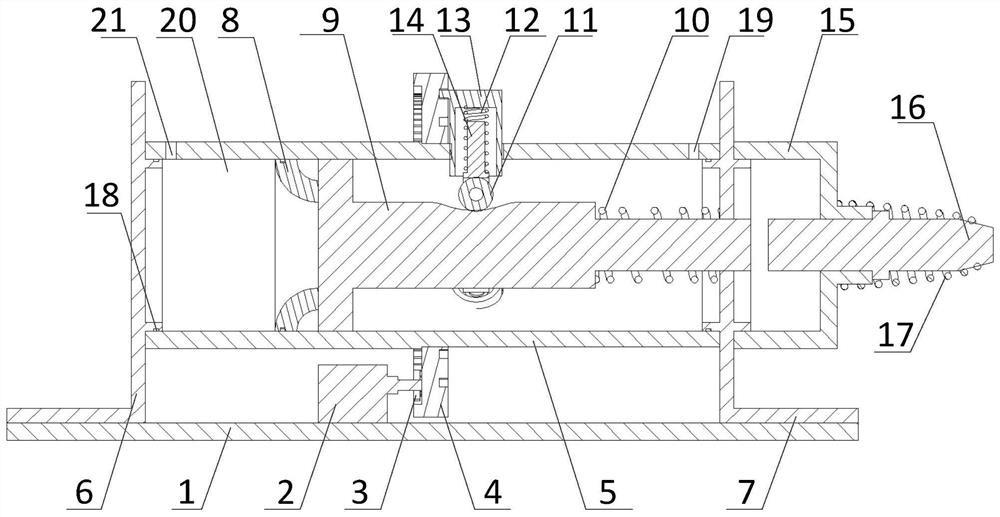
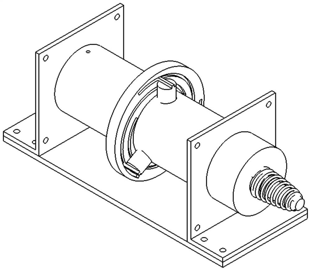
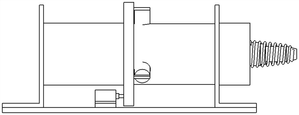
[0025] Such as figure 1 As shown, the specific implementation device includes a base plate 1, a servo motor 2, a gear 3, a gear helical groove plate 4, a main cylinder block 5, a rear end cover 6, a front end cover 7, an air storage ring 8, a cylinder main rod 9, Main rod back-moving spring 10, roller 11, sleeve compression spring assembly, cylinder secondary cylinder block 15, punching hammer 16 and punching hammer extension spring 17.

[0026] Such as figure 1 As shown, a front end cover 7 and a rear end cover 6 are respectively fixed on the front and rear sides of the base plate 1, a cylinder main cylinder body 5 is fixedly installed between the front end cover 7 and the rear end cover 6, and a cylinder is fixedly installed on the front end surface of the front end cover 7. Secondary cylinder block 15, cylinder sub-cylinder block 15 and cylinder main cylinder block...


PUM


Abstract

The invention discloses an impact force controllable pneumatic hammer riveting device. A cylinder main body and a cylinder secondary body are arranged on a bottom plate. Cylinder front and rear air holes are formed in the cylinder main body. A cylinder main rod is sleeved with the interior of the cylinder main body. A plurality of inner grooves are formed in the cylinder main rod. A gear spiral slotted disc is mounted on the outside of the cylinder main body. A gear of a servo motor is engaged with a gear ring of an annular groove of the gear spiral slotted disc. The gear spiral slotted disc is provided with a plurality of archimedes spiral grooves. A sleeve compressed spring assembly matched with the archimedes spiral grooves is arranged in front of the gear spiral slotted disc and comprises a roller compressed spring, a sleeve, a roller supporting rod and a roller. A punch hammer is movably mounted in a horizontal central through hole of the cylinder secondary body. According to theimpact force controllable pneumatic hammer riveting device, the air accumulation pressure of an air accumulation cavity can be regulated, the pressure difference between the air pressure on the two sides of the cylinder main rod is changed, the impact force of the punch hammer is controlled, the stability of impact energy is guaranteed, high-precision efficient pneumatic hammer riveting can be achieved, and the impact force controllable pneumatic hammer riveting device has the characteristics of zero oil pollution and convenient carrying.

Description

technical field [0001] The invention belongs to a pneumatic hammer riveting device in the technical field of pneumatics, and relates to a pneumatic hammer riveting device with controllable impact force. Background technique [0002] With the rapid development of the aviation industry, as the main connection method of aviation thin-walled parts, riveting and its equipment and technology have also received more and more attention and promotion. Both domestic and foreign scientific research and industrial practice have shown that riveting force or energy control is more conducive to the fatigue resistance of riveted joints than traditional riveting displacement control. [0003] Pneumatic riveting is the longest and most widely used riveting technology in current aviation manufacturing. Due to its advantages of strong flexibility, stable performance, clean and pollution-free, etc., it still occupies an extremely important position in the connection of aviation thin-walled parts...

Claims


Application Information

Patent Timeline
Patent Type & Authority Patents(China)
IPC IPC(8): B21J15/18F15B15/14
CPCB21J15/18F15B15/1423F15B15/1442
Inventor 宦红伦
Owner ZHEJIANG WANLI UNIV
Features
  • R&D
  • Intellectual Property
  • Life Sciences
  • Materials
  • Tech Scout
  • Unparalleled Data Quality
  • Higher Quality Content
  • 60% Fewer Hallucinations
Learn More