Piston ring casting technology
A casting process and piston ring technology, which is applied in the field of piston ring casting technology, can solve the problems of lower production efficiency, low production efficiency, and high labor intensity, and achieve the effect of improving casting efficiency and sand mold production efficiency
- Summary
- Abstract
- Description
- Claims
- Application Information
AI Technical Summary
Problems solved by technology
Method used
Image

Examples
Embodiment 1
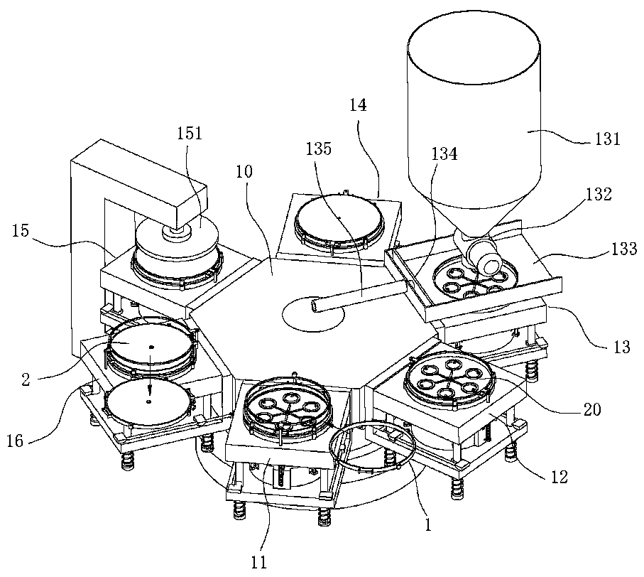
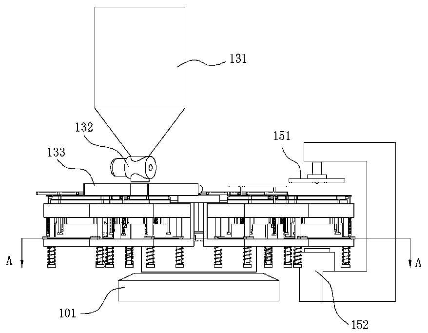
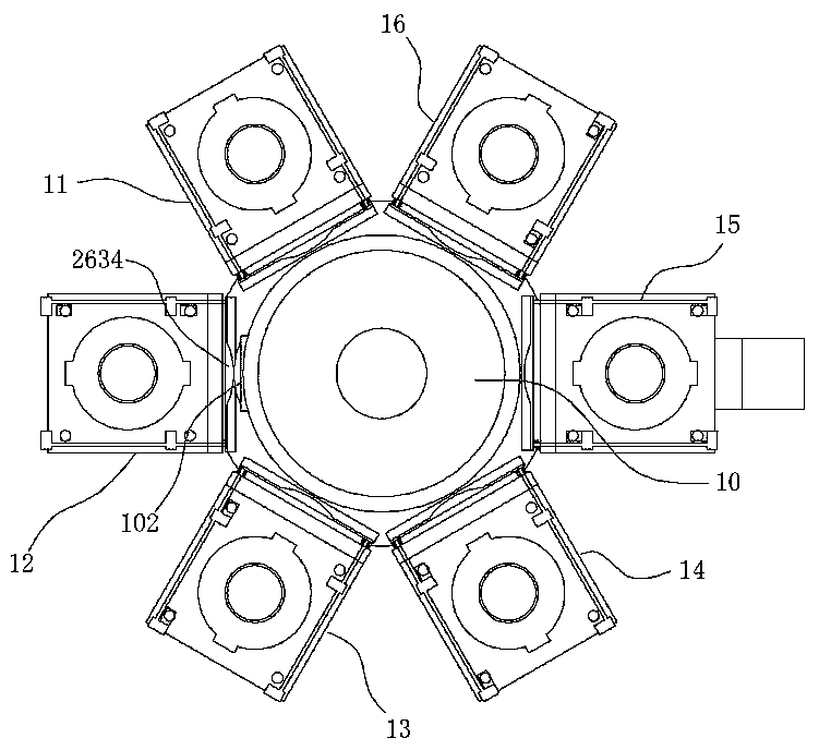
[0043] like Figure 1-3 As shown, a six-station sand molding machine includes a rotary support 10, the rotary support 10 is rotatably arranged on the machine base 101 along the vertical axis, and the circumferential surface of the rotary support 10 is equidistantly spaced along the circumferential direction. Six sand molds 20, and the positions of the six sand molds 20 on the sides of the rotary support 10 are respectively provided with a mold frame feeding station 11, a mold frame closing station 12, a sand filling station 13, and a manual inspection station. 14. Pressurization station 15 and sand mold unloading station 16; the sand mold 20 includes a base 26, a lower formwork 21 that is movably connected to the base 26 in the vertical direction, and a surrounding wall that is movably connected to the lower formwork 21 in the vertical direction. Plate 22; the top surface of the lower template 21 is provided with a punch 211 for forming a sand mold cavity, and the frame loadin...
Embodiment 2
[0053] A piston 233 ring casting process, comprising the steps of:
[0054] Step 1: Make the piston 233 ring sand mold, one end of the sand mold has a cavity and a horizontal runner, and the center of the sand mold has a longitudinal runner through the sand mold;
[0055] Step 2: Stack multiple sand molds together, and ensure that the longitudinal sprues of each sand mold are connected to each other. Set a bottom plate at the bottom of the bottom sand mold, and set a top mold with a pouring gate on the upper end of the uppermost sand mold. The pouring gate and the lower sand mold The vertical sprue is connected;
[0056] Step 3: Transfer the stacked sand molds to the pouring area, inject molten iron into the sand molds through the pouring port, the temperature of the molten iron is not lower than 1500°C, and the pouring temperature is not lower than 1350°C;
[0057] Step 4: Cool the sand mold after pouring to room temperature, and then perform sand removal treatment to clean ...
PUM
 Abstract
Description
Claims
Application Information
 - Generate Ideas
- Intellectual Property
- Life Sciences
- Materials
- Tech Scout
- Unparalleled Data Quality
- Higher Quality Content
- 60% Fewer Hallucinations
Browse by: Latest US Patents, China's latest patents, Technical Efficacy Thesaurus, Application Domain, Technology Topic, Popular Technical Reports.
© 2025 PatSnap. All rights reserved.Legal|Privacy policy|Modern Slavery Act Transparency Statement|Sitemap|About US| Contact US: help@patsnap.com