Metal plate cutting machine for automobile production

A cutting machine, sheet metal technology, applied in the direction of shearing machine equipment, shearing device, metal processing equipment, etc., can solve the problems of sheet metal dislocation, large sheet metal damage, etc., to improve friction, improve firmness, and improve fixing. the effect of

Inactive Publication Date: 2020-02-21
ZHUZHOU GUANG FENG ELECTRIC
View PDF9 Cites 2 Cited by
  • Summary
  • Abstract
  • Description
  • Claims
  • Application Information

AI Technical Summary

Problems solved by technology

[0004] Based on the existing vehicle sheet metal cutting machine, when the sheet metal is fixed, the damage to the sheet metal is relatively large. At the same time, the single point fixing makes the fixed sheet metal easy to be misplaced during cutting. The present invention proposes a Sheet metal cutting machine for vehicle production

Method used


Image

  • Metal plate cutting machine for automobile production
  • Metal plate cutting machine for automobile production
  • Metal plate cutting machine for automobile production

Examples


Embodiment 1

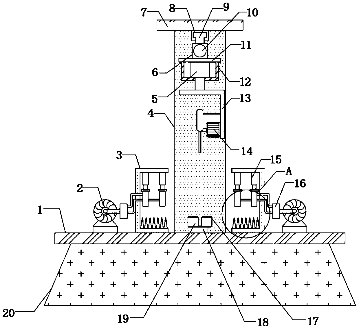
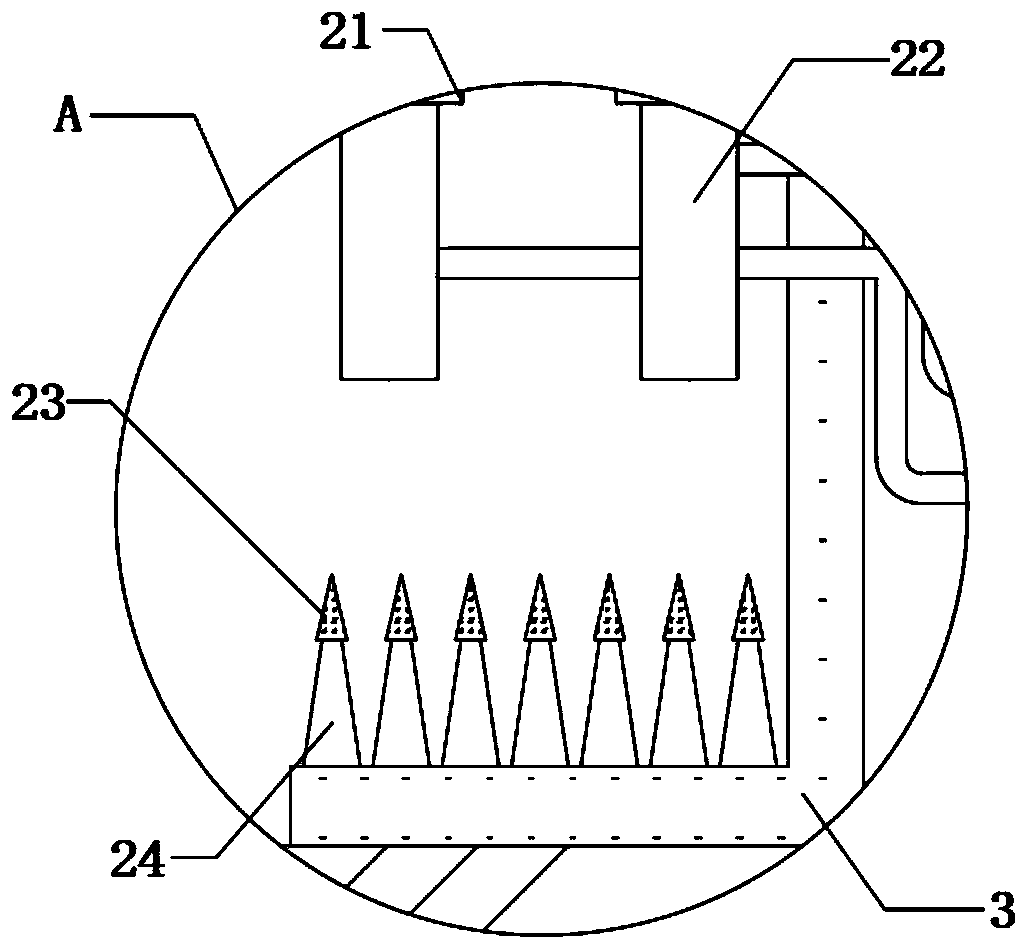
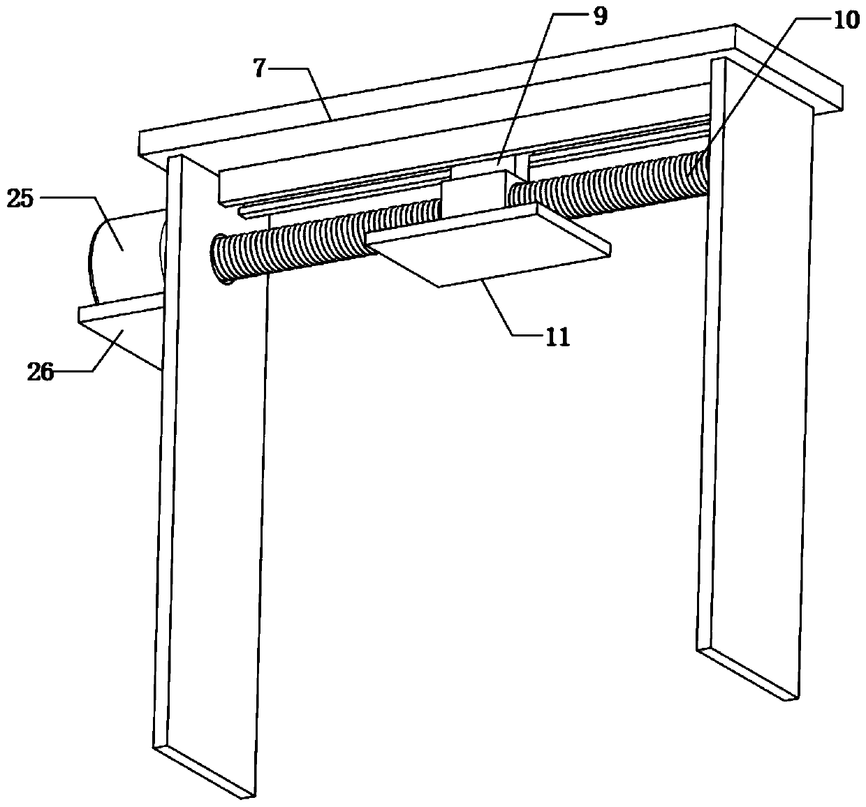
[0029] refer to Figure 1-5 , a sheet metal cutting machine for vehicle production, including a workbench 1, the top outer wall of the workbench 1 is fixed with two fixing frames 3 by screws, and the top inner walls of the two fixing frames 3 are fixed with four hydraulic rods by screws 15. The bottom outer walls of the two hydraulic rods 15 on the same horizontal line are fixed with the same adjustment plate 21 by screws, and the bottom outer walls of the adjustment plates 21 are equidistantly connected with fixed rods 22, and the fixed rods 22 on different adjustment plates 21 Arranged in a misplaced position, the outer wall of the top of the workbench 1 close to the fixed frame 3 is fixed with a suction pump 2 by screws, and the suction ends of the two suction pumps 2 are connected to a flow divider 16 through a pipeline, and the inner walls of a plurality of fixed rods 22 are connected to each other. There is an air hole 27, and each fixed rod 22 is connected to the divert...

Embodiment 2

[0040] refer to figure 1 , figure 2 , Figure 4 , Figure 5 and Figure 6, a sheet metal cutting machine for vehicle production, including a workbench 1, the top outer wall of the workbench 1 is fixed with two fixing frames 3 by screws, and the top inner walls of the two fixing frames 3 are fixed with four hydraulic rods by screws 15. The bottom outer walls of the two hydraulic rods 15 on the same horizontal line are fixed with the same adjustment plate 21 by screws, and the bottom outer walls of the adjustment plates 21 are equidistantly connected with fixed rods 22, and the fixed rods 22 on different adjustment plates 21 Arranged in a misplaced position, the outer wall of the top of the workbench 1 close to the fixed frame 3 is fixed with a suction pump 2 by screws, and the suction ends of the two suction pumps 2 are connected to a flow divider 16 through a pipeline, and the inner walls of a plurality of fixed rods 22 are connected to each other. There is an air hole 27...


PUM


Abstract

The invention belongs to the technical field of automobile production, and particularly relates to a metal plate cutting machine for automobile production. The problems that when a metal plate is fixed through an existing automobile metal plate cutting machine, the metal plate is severely damaged, and meanwhile, the fixed metal plate is prone to displacement during cutting due to single-point fixing are solved. The metal plate cutting machine comprises a workbench. Two fixing supports are arranged on the outer wall of the top of the workbench. Four hydraulic rods are arranged on the inner wallof the top of each fixing support. The outer walls of the bottoms of two hydraulic rods located on the same horizontal line are provided with one adjusting plate. The metal plate cutting machine is provided with the hydraulic rods, the adjusting plates and fixing rods, when the metal plate is fixed, the metal plate is fixed through the fixing rods arranged in a staggered mode, the area of connection points is increased, the fixing soundness is improved, meanwhile, in the fixing process, air passing holes of the fixing rods are vacuumed by a suction pump, the metal plate is further fixed through suction force, and damage to the metal plate is relieved while the fixing effect is improved.

Description

technical field [0001] The invention relates to the technical field of automobile production, in particular to a sheet metal cutting machine for vehicle production. Background technique [0002] Cars refer to vehicles or means of transportation that use wheels to rotate on land; vehicles come from the ancient method of measuring vehicles; vehicles at that time generally had two wheels, so a vehicle was called one or two when it was multiplied, and it was written as a vehicle later. During the production and processing of the vehicle, the sheet metal needs to be cut by a cutting machine. [0003] The existing sheet metal cutting machines for vehicle production have disadvantages in the process of use: before cutting, the sheet metal needs to be fixed by the fixing component, and when the sheet metal is fixed, the two ends of the sheet metal are fixed by the fixing component. In order to increase the firmness of the fixation, the extrusion strength of the fixing components to...

Claims


Application Information

Patent Timeline
Patent Type & Authority Applications(China)
IPC IPC(8): B23D19/00B23D33/02
CPCB23D19/00B23D33/02
Inventor 郑斌
Owner ZHUZHOU GUANG FENG ELECTRIC
Why Eureka
Try Eureka