Supercharge Your Innovation With Domain-Expert AI Agents!

Blade polishing device and polishing method

A polishing device and blade technology, which is applied in grinding/polishing safety devices, filing/filing devices, grinding/polishing equipment, etc., can solve the problems of inability to guarantee product consistency, difficulty in polishing blades, and low polishing pass rate and other problems to achieve the effect of eliminating microscopic defects on the surface, improving the quality of the working environment, and improving the surface quality

Active Publication Date: 2021-11-09
AECC AVIATION POWER CO LTD
View PDF0 Cites 0 Cited by
  • Summary
  • Abstract
  • Description
  • Claims
  • Application Information

AI Technical Summary

Problems solved by technology

[0002] The structure of the blade is complex, and the curvature of the blade shape changes greatly. After milling, the milling tool marks are removed by manual polishing and the surface roughness is improved. Manual polishing can flexibly remove the tool marks at different positions of the blade, but manual polishing depends on the experience of the workers, resulting in individual differences in the blades. Huge, unable to guarantee product consistency, low polishing pass rate (one-time inspection pass rate <30%, out-of-tolerance use <70%); some blades are difficult to polish, and only a few workers in the entire factory can perform polishing work, resulting in low production capacity , a large number of blades are backlogged in the polishing process; the effective working time of workers is less than 4 hours (statistically based on 8 hours of working time), the production efficiency is low, and the working environment is harsh (noise, dust, darkness); polishing a blade needs to change 3 to 5 mills head, each grinding head polishes 4 to 5 leaves on average

Method used


Image

  • Blade polishing device and polishing method
  • Blade polishing device and polishing method
  • Blade polishing device and polishing method

Examples


Embodiment Construction

[0030] In order to make the purpose, technical solutions and advantages of the embodiments of the present invention clearer, the technical solutions of the present invention will be clearly and completely described below in conjunction with the accompanying drawings. Obviously, the described embodiments are part of the embodiments of the present invention, not all of them. the embodiment. Based on the embodiments of the present invention, all other embodiments obtained by persons of ordinary skill in the art without making creative efforts belong to the protection scope of the present invention.

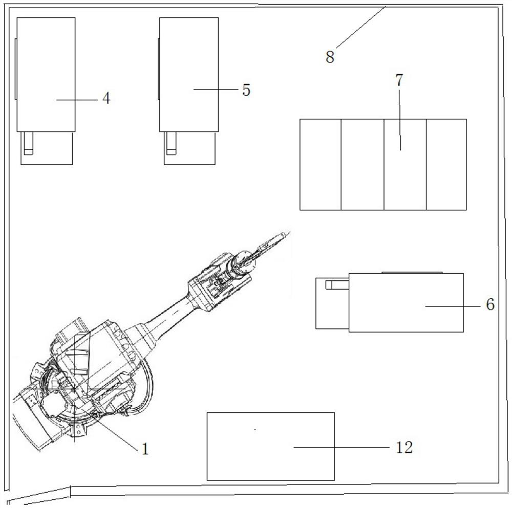
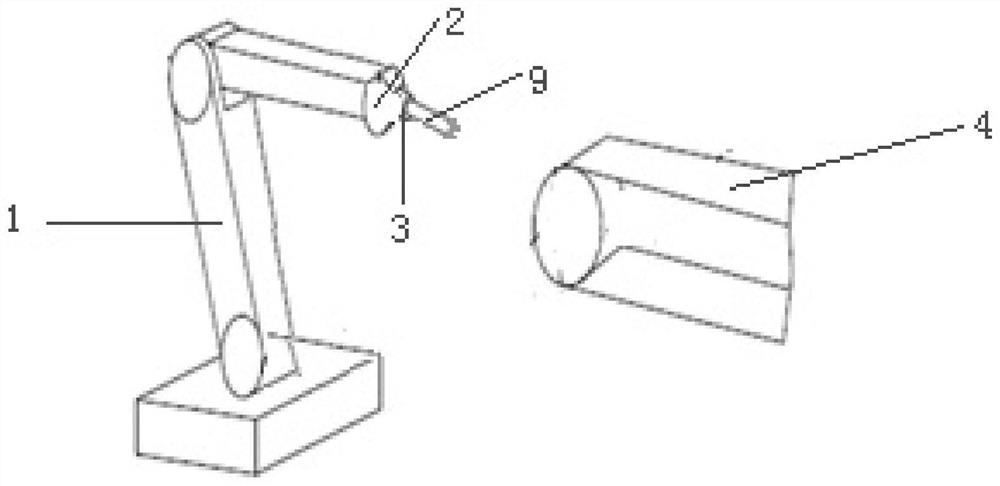
[0031] As a certain preferred embodiment of the present invention, such as figure 1 with figure 2 As shown, a blade polishing device includes an industrial robot 1, a force control device 2, a clamping tool 3, a first polishing machine 4, a second polishing machine 5, a third polishing machine 6, a dust removal device 7 and a laser The calibration device, the industrial robot 1 ha...


PUM


Abstract

The invention discloses a blade polishing device and a polishing method, comprising an industrial robot, a force control device, a clamping tool, a first polishing machine, a second polishing machine, and a third polishing machine. The force control device is installed on the industrial robot The end of the mechanical arm, the clamping tool is connected with the force control device, the first polishing machine, the second polishing machine and the third polishing machine are distributed around the industrial robot; the clamping tool is used to clamp the blade, and the force control device It is used to adjust the contact pressure between the blade and the polishing machine, the first polishing machine is used to polish the blade profile, the second polishing machine is used to polish the inlet edge and exhaust edge of the blade, and the third polishing machine is used for Grinding blade edge plates and for glazing blade profiles, blade inlet and outlet edges. The force control device sets the contact pressure between the blade and the polishing machine, which ensures the removal amount of different blade sections during the grinding process, and the different positions of the polishing machine meet the requirements of different positions and precision of the blade.

Description

technical field [0001] The invention belongs to the field of mechanical polishing, and in particular relates to a blade polishing device and a polishing method. Background technique [0002] The structure of the blade is complex, and the curvature of the blade shape changes greatly. After milling, the milling tool marks are removed by manual polishing and the surface roughness is improved. Manual polishing can flexibly remove the tool marks at different positions of the blade, but manual polishing depends on the experience of the workers, resulting in individual differences in the blades. Huge, unable to guarantee product consistency, low polishing pass rate (one-time inspection pass rate <30%, out-of-tolerance use <70%); some blades are difficult to polish, and only a few workers in the entire factory can perform polishing work, resulting in low production capacity , a large number of blades are backlogged in the polishing process; the effective working time of worker...

Claims


Application Information

Patent Timeline
Patent Type & Authority Patents(China)
IPC IPC(8): B24B27/00B24B21/16B24B21/18B24B21/20B24B29/02B24B41/06B24B49/12B24B51/00B24B55/06B23D71/00B25J11/00
CPCB23D71/005B24B21/165B24B21/18B24B21/20B24B27/0023B24B29/02B24B41/06B24B49/12B24B51/00B24B55/06B25J11/0065
Inventor 余杰种磊吴晓锋王伟涛王芳刘志军汤丽周峰
Owner AECC AVIATION POWER CO LTD
Features
  • R&D
  • Intellectual Property
  • Life Sciences
  • Materials
  • Tech Scout
  • Unparalleled Data Quality
  • Higher Quality Content
  • 60% Fewer Hallucinations
Learn More