Edge cutting device for film layering

A technology of trimming and filming, which is applied in the field of trimming devices for film layering, which can solve the problems of irregular film shape, large film cutting area, unstable operation of equipment, etc., and achieve the effect of low cost and simple operation

Active Publication Date: 2020-02-21
CHONGQING RUITING PLASTIC
View PDF7 Cites 5 Cited by
  • Summary
  • Abstract
  • Description
  • Claims
  • Application Information

AI Technical Summary

Problems solved by technology

[0004] During the long-distance processing and transmission of the film, it is often due to the unstable operation of the equipment, or the material is shifted to one side due to changes in the external environment. When the shifted film enters the cutting equipment for cutting, it is

Method used


Image

  • Edge cutting device for film layering
  • Edge cutting device for film layering
  • Edge cutting device for film layering

Examples


Embodiment 1

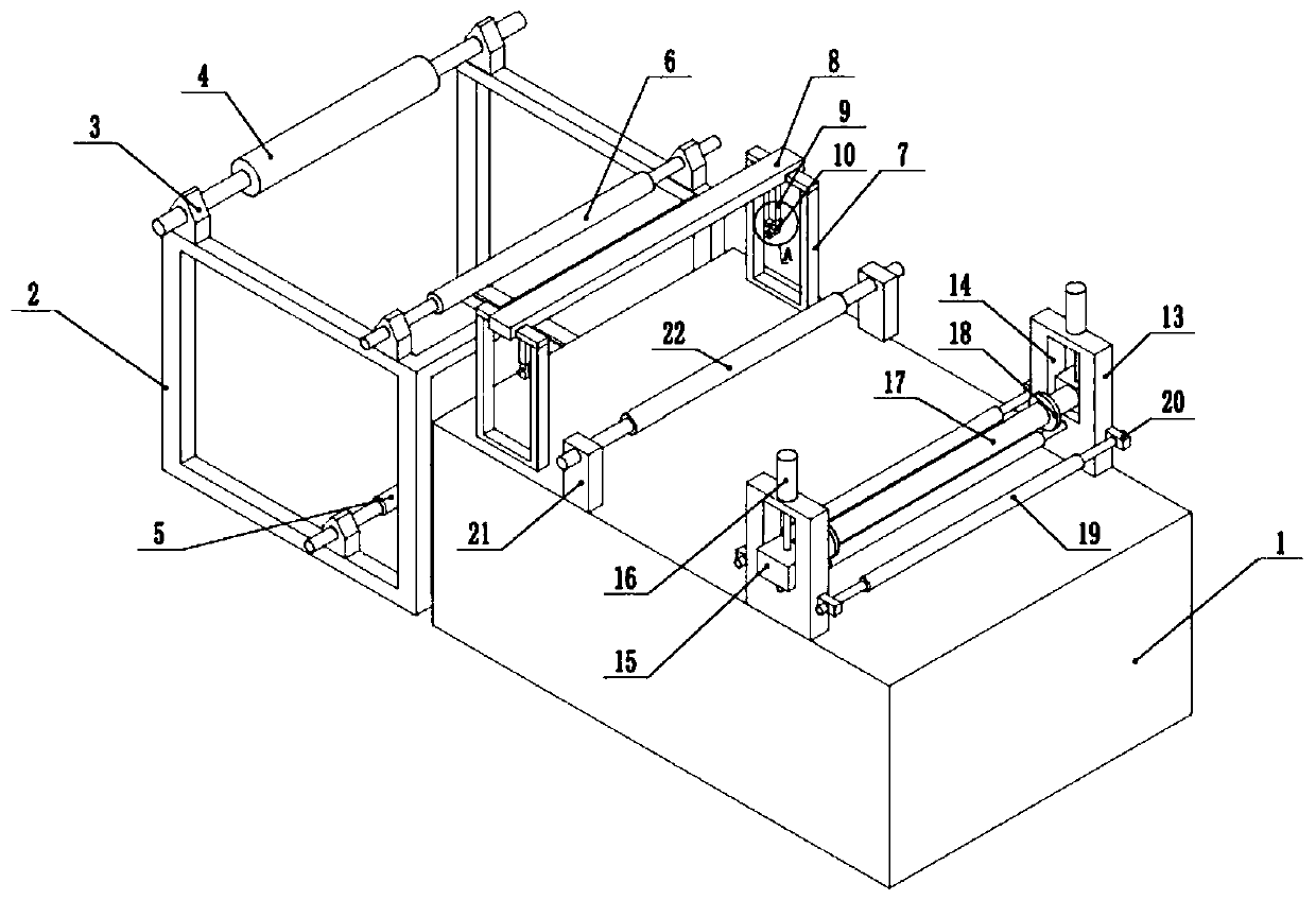
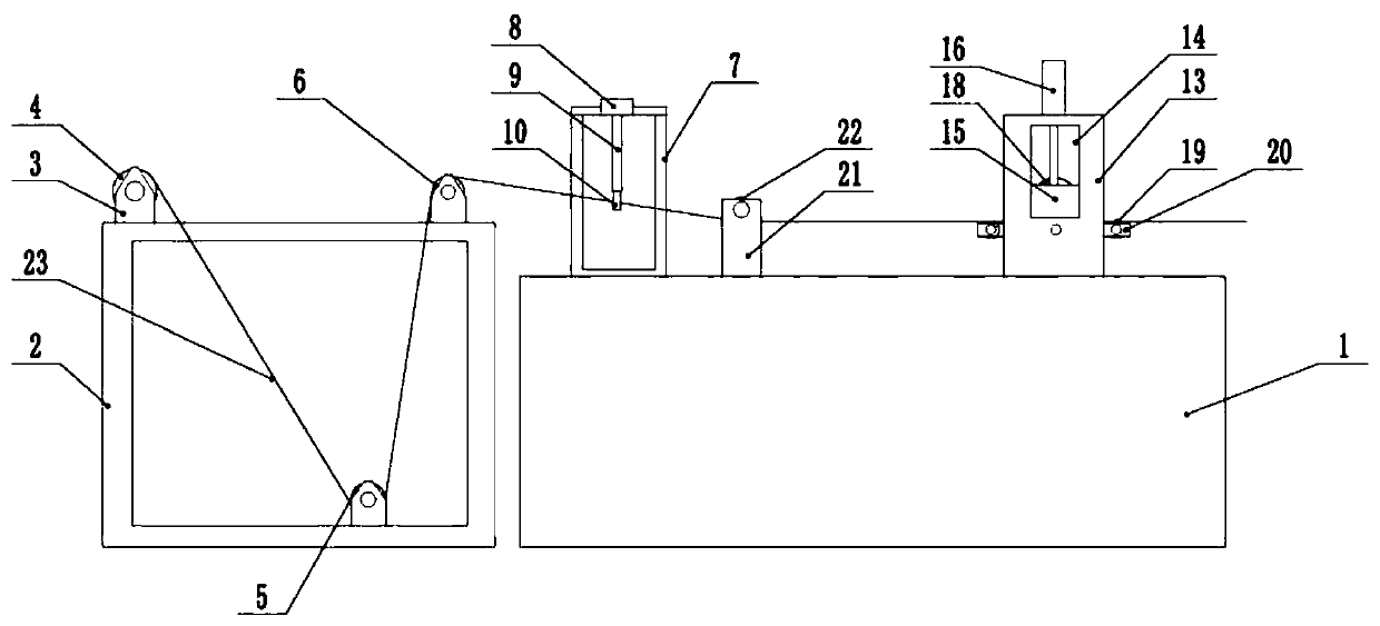
[0039] The embodiment is basically as attached figure 1 and figure 2 Shown: the trimming device for film layering, including workbench 1, the left side of workbench 1 is provided with frame 2, and frame 2 is fixedly connected with the ground by bolts.

[0040] The upper end of the frame 2 is provided with the first traction roller 4 and the third traction roller 6 successively from left to right, the lower end of the frame 2 is provided with the second traction roller 5, and the second traction roller 5 is located between the first traction roller 4 and the third traction roller. Between the rollers 6, in the present embodiment, the two ends that are provided with the first traction roller 4, the two ends of the second traction roller 5 and the two ends of the third traction roller 6 are all provided with a rotating seat 3, and the rotating seat 3 is all connected with The frame 2 is welded and fixed, the two ends of the first traction roller 4, the two ends of the second tr...

Embodiment 2

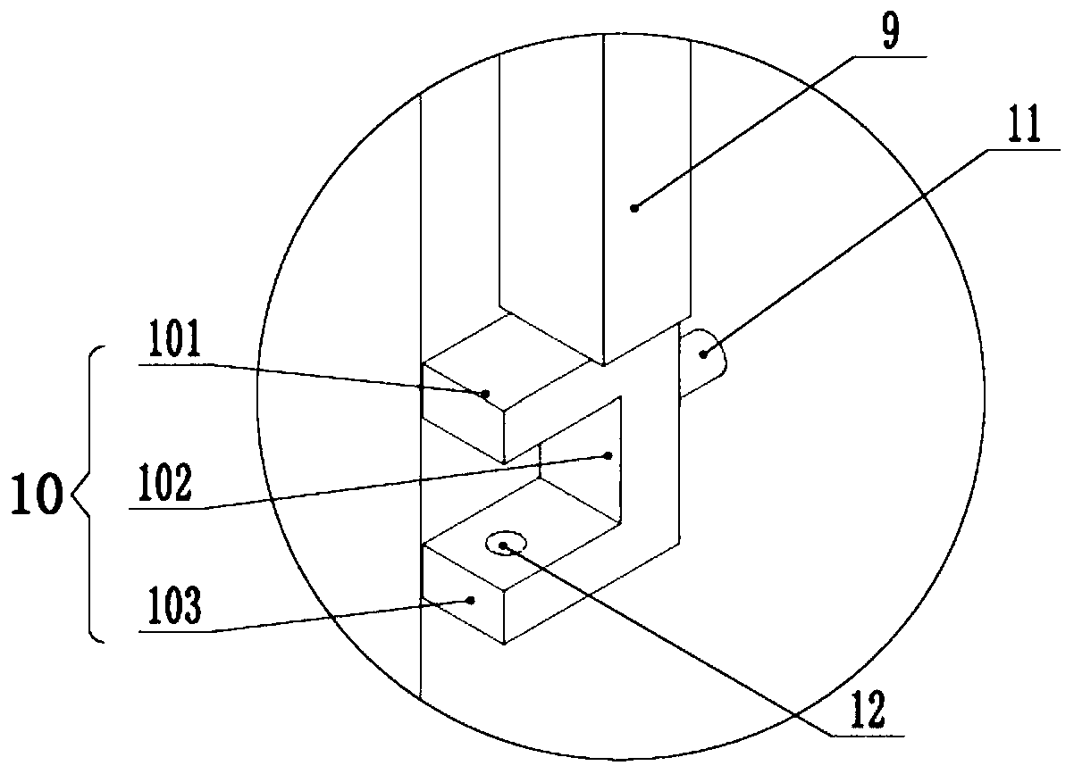
[0051] Such as Figure 4 and Figure 5 As shown, the edge trimming device for film layering differs from the first embodiment in that the connection plate 9 and the support plate 8 are slidably connected in this embodiment, and the connection plates 9 all slide along the length direction of the support plate 8 . Specifically: the support plate 8 is provided with a rectangular chute 28 along its length direction. The chute 28 is a through-slot structure. The end of the connecting plate 9 away from the deviation correction block 10 passes through the chute 28, and the connection plate 9 is far away from the deviation correction. One end of the block 10 is welded and fixed with a slide plate 29 of a rectangular plate structure, the slide plate 29 is vertically arranged with the connecting plate 9, and the length of the slide plate 29 is greater than the width of the chute 28 .

[0052] The upper end of the support plate 8 and both sides of the sliding groove 28 are provided with...


PUM


Abstract

The invention belongs to the technical field of film edge cutting and particularly discloses an edge cutting device for film layering. The edge cutting device comprises a working table. The working table is sequentially provided with a deviation rectifying unit and an edge cutting unit in the conveying direction of films. The deviation rectifying unit comprises two deviation rectifying frames. Thetwo deviation rectifying frames are located on the two sides of the working table correspondingly. The two deviation rectifying frames are symmetrically arranged. Deviation rectifying blocks are correspondingly connected to the two deviation rectifying frames. The two deviation rectifying blocks are half I-shaped, the two deviation rectifying blocks are symmetrically arranged, and the deviation rectifying blocks are internally hollow. Air outlets right facing each other are formed in the upper sides and the lower sides of the deviation rectifying blocks. Air inlets are formed in the side walls of the deviation rectifying blocks. The air inlets are communicated with an air supply unit for introducing air to the deviation rectifying blocks. The edge cutting unit comprises two edge cutting frames. A cutting rod is connected between the two edge cutting frames, and cutters are correspondingly connected to the two ends of the cutting rod. According to the edge cutting device for film layering, the deviated thin films can be rectified, and the cut films are regular in shape.

Description

technical field [0001] The application of the present invention belongs to the technical field of film edge trimming, and specifically discloses an edge trimming device for film layering. Background technique [0002] Existing plastic film blowing machine is to be by extruder (extruder is molten state after plastics is through heating, extruding, is extruded by die head again, is blown into film bubble by compressed air simultaneously, the cross section of film bubble ring), and a traction roller installed above the die head and a take-up device, and a herringbone plate is arranged under the traction roller, through which the film bubble blown by the extruder die head Before coiling, it is extruded into two layers of interconnected flat films for coiling (because the cross-section of the bubble is circular, the bubble will be extruded into two layers of film after being squeezed by the herringbone plate ). [0003] Before the film is rolled up in the later stage, it is usu...

Claims


Application Information

Patent Timeline
IPC IPC(8): B26D7/06B26D7/08B26D7/02B26D1/22B26D7/26B29C55/28
CPCB26D1/225B26D7/025B26D7/0683B26D7/08B26D7/2635B26D2007/082B29C55/28B29C2793/0063B29C2793/009
Inventor 曹玉毛潞
Owner CHONGQING RUITING PLASTIC
Why Eureka
Try Eureka