
Straw compression device for corn harvesting machine

A corn harvester and compression device technology, applied in the direction of presses, manufacturing tools, etc., can solve the problems of limited space of the corn harvester, affect the operation speed, inconvenience, etc., achieve fast and efficient compression operation, improve operation efficiency, and take up space. small effect

Pending Publication Date: 2020-02-21
LUOYANG FERGUSON MECHANICAL EQUIP
View PDF0 Cites 0 Cited by
  • Summary
  • Abstract
  • Description
  • Claims
  • Application Information

AI Technical Summary

Problems solved by technology

[0003] The existing corn harvester realizes the recycling of straw by cutting and crushing the straw, but due to the limited space of the corn harvester, the crushed straw cannot be stored too much, and the crushed straw needs to be removed after a period of operation. Therefore, it is necessary to pick up the straw, which not only affects the operation speed, but also needs to pick up the thrown straw, which increases the labor load and is very inconvenient. The current solution is to pick up the crushed straw Compression to save space, existing compression devices are too inefficient for fast-working corn harvesters

Method used


Image

  • Straw compression device for corn harvesting machine
  • Straw compression device for corn harvesting machine
  • Straw compression device for corn harvesting machine

Examples


Embodiment Construction

[0021] The technical solutions in the embodiments of the present invention will be clearly and completely described below in conjunction with the accompanying drawings in the embodiments of the present invention. Obviously, the described embodiments are only some of the embodiments of the present invention, not all of them (for It is convenient to describe and understand, the following figure 2 above is above, figure 2 The front of the front is described as the front). Based on the embodiments of the present invention, all other embodiments obtained by persons of ordinary skill in the art without making creative efforts belong to the protection scope of the present invention.

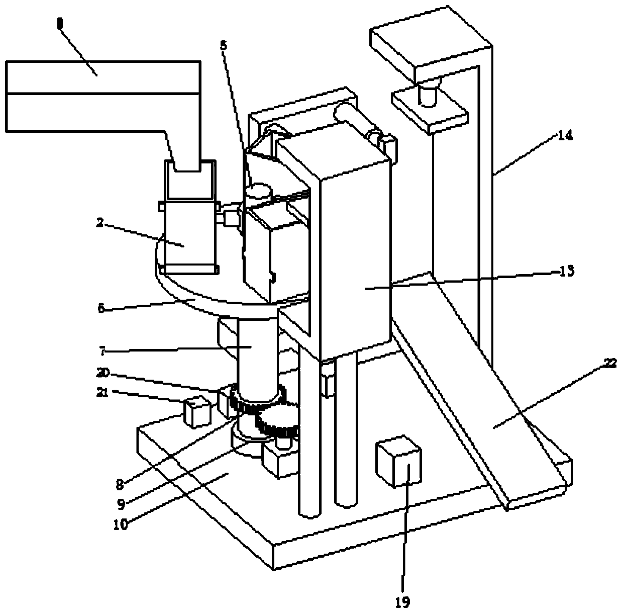
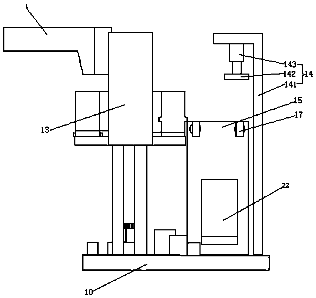
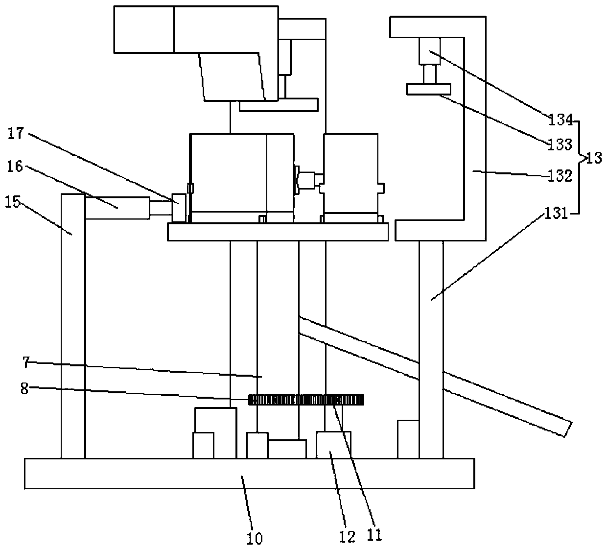
[0022] see Figure 1-6 , the present invention provides a technical solution: a straw compression device for a corn harvester, comprising a feed inlet 1, a pressing box 2, a compacting device 13 and a mounting plate 10, the upper surface of the mounting plate 10 is rotatably connected by a bearing 9...


PUM


Abstract

The invention discloses a straw compression device for a corn harvesting machine. A feeding port, pressing boxes, a compaction device and an installing plate are included. The upper surface of the installing plate is rotationally connected with a rotation shaft through a bearing. The outer side face of the rotation shaft is in cup joint with a driven gear. One side of the driven gear is in meshingconnection with a drive gear. The drive gear is fixedly connected with a motor output shaft arranged at the lower end of the drive gear. A supporting column is arranged at the middle position of theupper surface of a rotation disc. Three first hydraulic telescopic rods are evenly distributed on the outer side face of the supporting column. The tail ends of the first hydraulic telescopic rods areprovided with the pressing boxes. Each pressing box comprises a box body, a bottom plate which is in sliding connection with the box body and a magnet, wherein the magnet is arranged on the outer side face of one end of the bottom plate. The feeding port is formed over the pressing boxes. The compaction device is arranged in front of the rotation disc. According to the straw compression device for the corn harvesting machine, through the arrangement of the pressing boxes working through rotation, the compaction device is used for compressing straw, and the compression efficiency is greatly improved.

Description

technical field [0001] The invention relates to the technical field of corn harvesters, in particular to a straw compression device for corn harvesters. Background technique [0002] With the development of agricultural intelligence and convenience, the functions of the corn harvester are becoming more and more complete, from cutting corn stalks to corn threshing can be realized by the corn harvester. [0003] The existing corn harvester realizes the recycling of straw by cutting and crushing the straw, but due to the limited space of the corn harvester, the crushed straw cannot be stored too much, and the crushed straw needs to be removed after a period of operation. Therefore, it is necessary to pick up the straw, which not only affects the operation speed, but also needs to pick up the thrown straw, which increases the labor load and is very inconvenient. The current solution is to pick up the crushed straw Compression is performed to save space, and existing compression...

Claims


Application Information

Patent Timeline
IPC IPC(8): B30B9/30B30B15/32B30B15/26B30B15/00
CPCB30B9/3007B30B9/3014B30B9/306B30B9/3003
Inventor 赵越云王喜龙梁晓剑亓明亮李二帅
Owner LUOYANG FERGUSON MECHANICAL EQUIP
Learn More