Helicopter landing probe device and control method thereof
A rod device and helicopter technology, applied in the direction of aircraft landers, etc., can solve the problems of lack of protection function and the inability of free expansion and contraction of the landing probe rod, and achieve the effect of benefiting the radial direction and improving the radial bearing capacity
- Summary
- Abstract
- Description
- Claims
- Application Information
AI Technical Summary
Problems solved by technology
Method used
Image

Examples
Embodiment 1
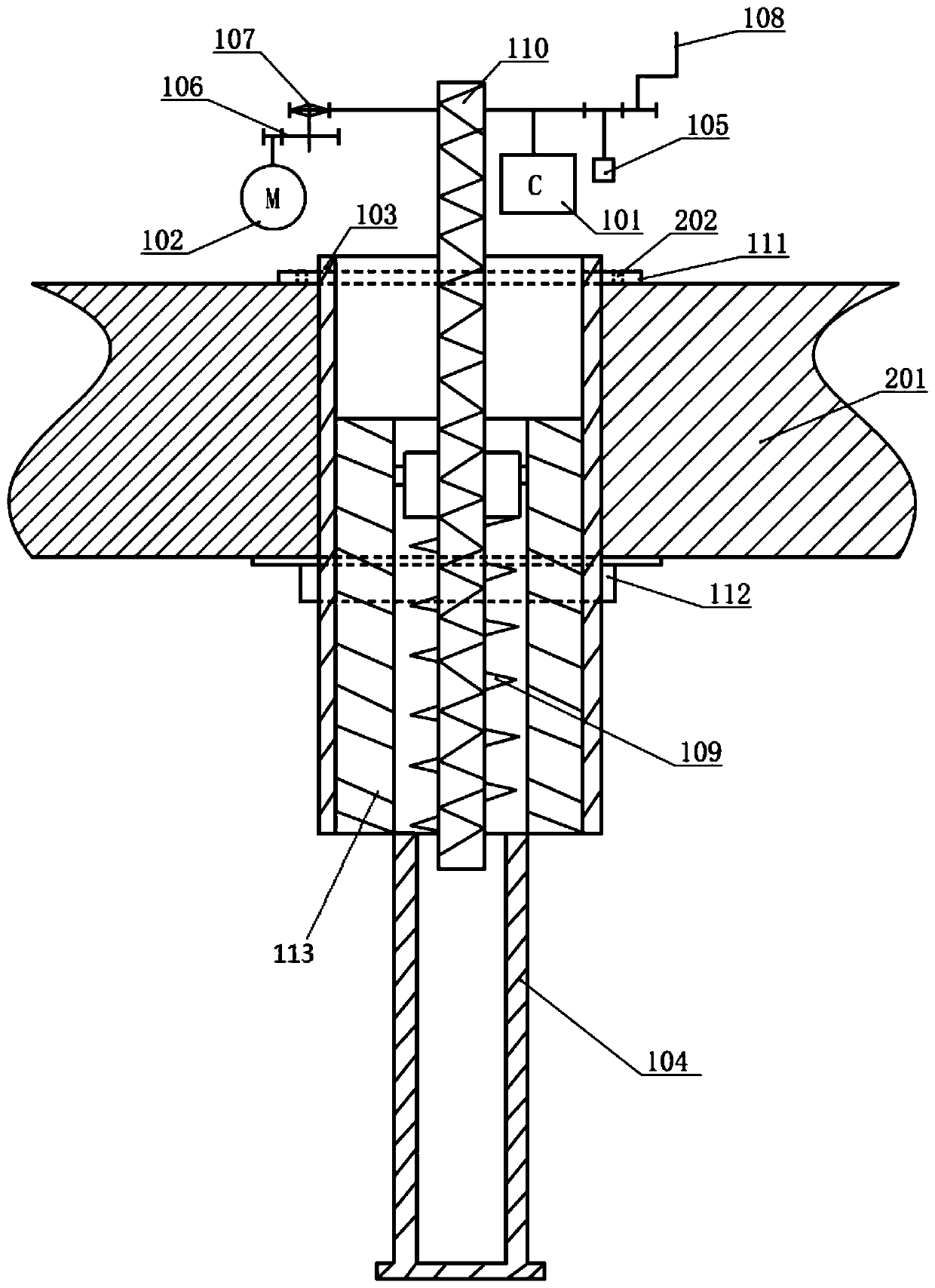
[0031] figure 1 For landing probe device and installation diagram, such as figure 1 As shown, this embodiment provides a helicopter landing probe device, which includes a controller 101, a motor 102, a clutch 107, a linear motion mechanism 110, a probe rod, and an elastic member 109,
[0032] The controller 101 is electrically connected to the motor 102, and the controller 101 controls the operation of the motor 102;
[0033] The motor 102 and the clutch 107, the output end of the motor 102 is connected to the clutch 107, and the clutch 107 is connected to the linear motion mechanism 110; the motor 102 drives the clutch 107 to drive the linear motion mechanism 110 in the vertical direction movement;
[0034] The probe includes a housing 103, a probe body 113 and a probe shaft 104. The housing 103 is fixed on the body structure 201, and the probe body 113 is slidably sleeved in the housing 103; The linear motion mechanism 110 passes through the through hole of the probe body 113 and ...
Embodiment 2
[0047] This embodiment provides a method for controlling a helicopter landing probe rod, using the above-mentioned helicopter landing probe rod device, and the method includes:
[0048] Adjust the power switch to the on state, the controller 101 is energized and self-checked, and feedback the fault information of the controller 101;
[0049] If the self-check shows that the controller 101 is faulty, the hand crank mechanism 108 is used to drive the linear motion mechanism 110 to move in the vertical direction;
[0050] If the self-inspection shows that the controller 101 is normal, adjust the probe rod retracting and releasing switch to the probe rod retracting position or releasing position. The motor 102 drives the clutch 107 to drive the linear motion mechanism 110 to rise or fall in the vertical direction, and the linear motion mechanism 110 The probe body 113 and the probe shaft 104 are driven to rise or fall in the vertical direction.
[0051] Further, the method includes, when ...
Embodiment 3
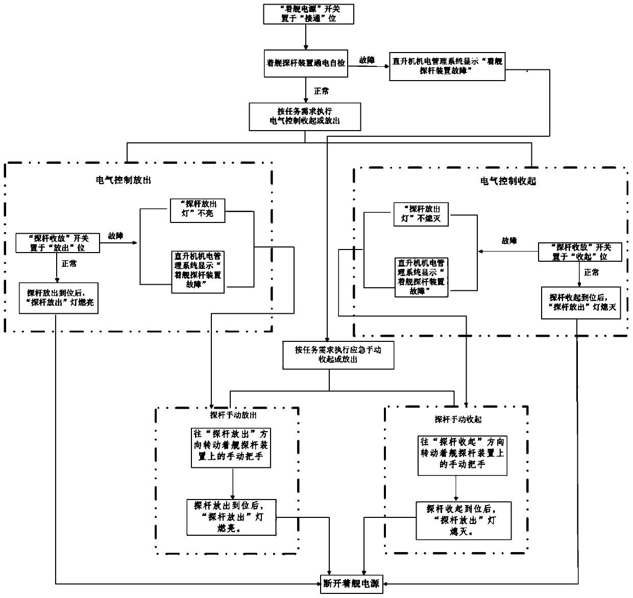
[0055] Combine image 3 , image 3 The control flow chart of the probe rod device for landing, combined with figure 1 , figure 2 with image 3 As shown, the actual control principle of the present invention is as follows.
[0056] A. Method of electrical control release
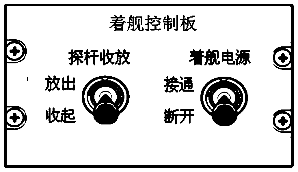
[0057] 1) Set the power switch on the landing control board to the "on" position, and the landing probe device is powered on for self-check. If the self-check fails, the fault information will be sent to the helicopter electromechanical management system. The helicopter electromechanical management system displays "failure of the landing probe device". At this time, the emergency manual release operation can only be used.
[0058] 2) When the power-on self-check is normal, set the "probe retracting and releasing switch" switch on the landing control board to the "release" position, and the probe will actuate to release. After the probe is released in place, the indicator light will light up. The indicator light...
PUM
 Abstract
Description
Claims
Application Information
 - R&D
- Intellectual Property
- Life Sciences
- Materials
- Tech Scout
- Unparalleled Data Quality
- Higher Quality Content
- 60% Fewer Hallucinations
Browse by: Latest US Patents, China's latest patents, Technical Efficacy Thesaurus, Application Domain, Technology Topic, Popular Technical Reports.
© 2025 PatSnap. All rights reserved.Legal|Privacy policy|Modern Slavery Act Transparency Statement|Sitemap|About US| Contact US: help@patsnap.com