System and method for taking water from side wall of karst water level fluctuating cave

A sinking and karst technology, applied in water supply devices, drinking water devices, buildings, etc., can solve the problems of deep sinking holes, pumping groundwater, and large changes in water levels, etc., to solve the problem of water shortage, easy to implement, and simple in construction Effect

Pending Publication Date: 2020-02-21
重庆市二零八地质环境研究院有限公司
View PDF0 Cites 0 Cited by
  • Summary
  • Abstract
  • Description
  • Claims
  • Application Information

AI Technical Summary

Problems solved by technology

Rainwater quickly enters underground sinkholes and underground rivers through ground runoff, and the water level is buried deep. It is difficult to use the hidden underground water resources by simple pumping methods
[0003] During the survey, it was found that many sinkholes have water all year round, but the water level is relatively deep, and the shape of the sinkholes is irregular, there are dangerous rocks and rolling stones on the side walls, and there are overgrown weeds and bushes, so it is generally difficult to detect In the specific situation, there is no effective and feasible way to extract groundwater for human use
[0004] The existing method of drilling for water intake mostly adopts the method of drilling directly above the water source. However, due to a series of problems such as deep water level in the sinkhole, large changes in water level during drought and flood seasons, and silt at the bottom, the existing drilling for water intake The method cannot be effectively used on karst sinkholes

Method used


Image

  • System and method for taking water from side wall of karst water level fluctuating cave

Examples


Embodiment Construction

[0023] Below by embodiment and in conjunction with accompanying drawing, the present invention will be further described:

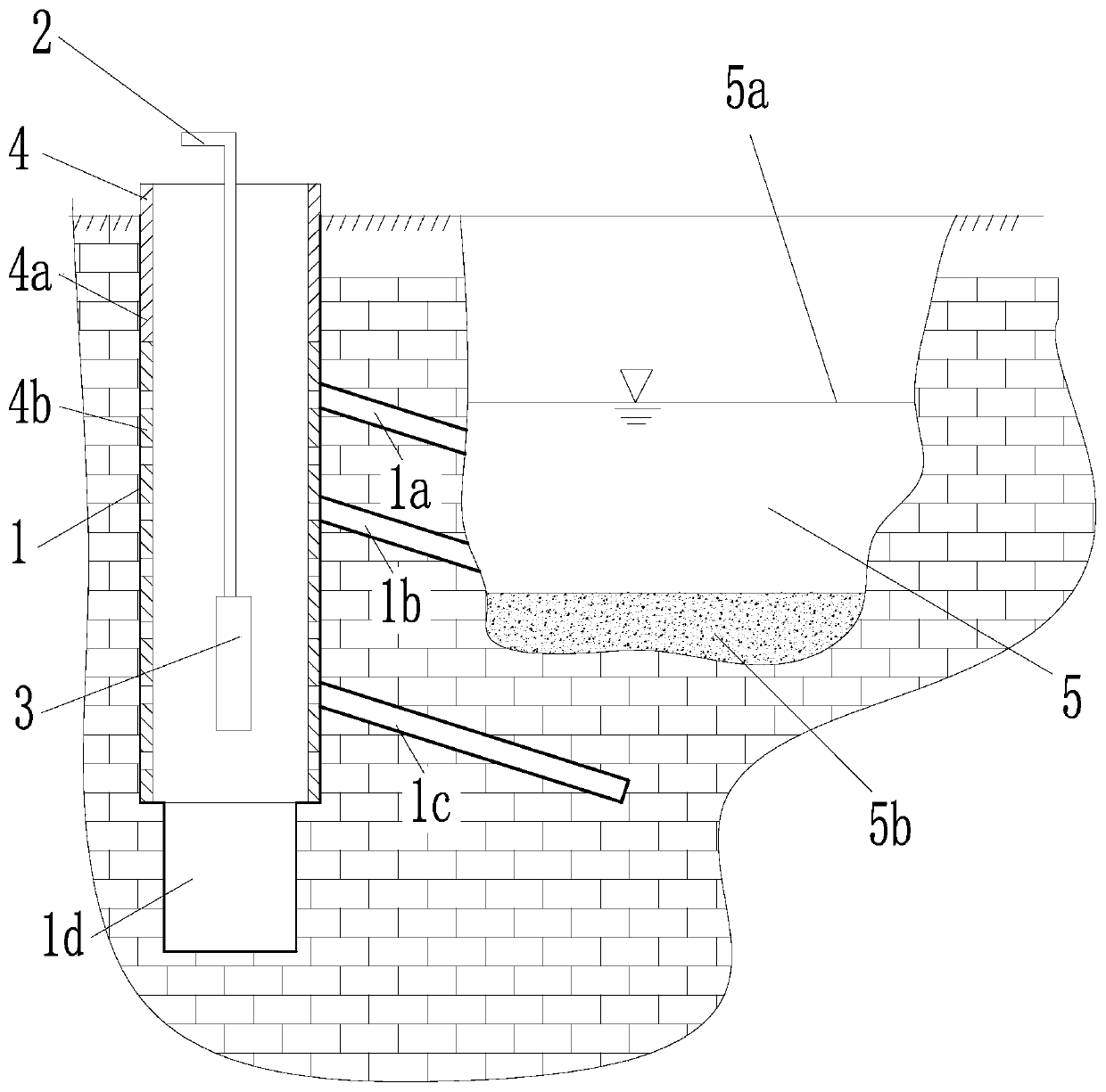
[0024] Such as figure 1 As shown, a water intake system for the side wall of a karst sinkhole is mainly composed of a water supply well 1, a water lift pipe 2, a water pump 3, and a wall protection pipe 4.

[0025] The water supply well 1 is a vertical borehole that is arranged on the complete bedrock 6 near the outside of the sinkhole 5 and is deeper than the sinkhole 5 . Preferably, the distance between the water supply well 1 and the sinkhole 5 is 4-8 meters, and the depth of the water supply well 1 exceeds the depth of the sinkhole 5 by 20-40 meters.

[0026] The diameter of the bottom of the borehole is smaller than the diameter of the main part of the borehole to form the sedimentation well section 1d. The main part of the borehole includes the upper solid pipe well section and the lower flower pipe well section, and a stepped surface is formed bet...


PUM


Abstract

The invention discloses a system and a method for taking water from the side wall of a karst water level fluctuating cave. A water supply well is a vertical borehole which is arranged on a complete bed rock close to the outer side of the water level fluctuating cave and has depth exceeding that of the water level fluctuating cave. A sand sediment trap section is arranged at the bottom of the borehole. A first-stage inclined branch hole, a second-stage inclined branch hole and a third-stage inclined branch hole which are gradually inclined downwards are drilled in the side wall of the water supply well from top to bottom sequentially. The first-stage inclined branch hole and the second-stage inclined branch hole communicate with the water supply well and the water level fluctuating cave respectively, and the ends of the first-stage inclined branch hole and the second-stage inclined branch hole are lower than the perennial water level of the water level fluctuating cave and higher than the silt seam of the water level fluctuating cave; and the third-stage inclined branch hole extends into the rock stratum below the water level fluctuating cave. A retaining wall pipe is located insidethe main body part of the borehole, and comprises a perforated pipe section at the lower part and a solid pipe section at the upper part. A water pump is installed in the retaining wall pipe and canpump water in the retaining wall pipe to the outside of the water supply well in combination with a lifting pipe. The invention also discloses a method for taking water from the side wall of the karstwater level fluctuating cave. Even if the water level keeps falling, underground water in the cave can be pumped, and thus, the problem about use of local water is effectively solved.

Description

technical field [0001] The invention belongs to the field of geological drilling engineering, and in particular relates to a water intake system for karst sinkholes and a water intake method using the water intake system. Background technique [0002] Due to its natural geography and stratum, the karst rocky mountain area has been in a state of water shortage for a long time, and it is quite difficult for people and animals to drink water. Rainwater quickly enters underground sinkholes and underground rivers through surface runoff, and the water level is buried deep. It is difficult to use the hidden underground water resources by simple pumping methods. [0003] During the survey, it was found that many sinkholes have water all year round, but the water level is relatively deep, and the shape of the sinkholes is irregular, there are dangerous rocks and rolling stones on the side walls, and there are overgrown weeds and bushes, so it is generally difficult to detect In the ...

Claims


Application Information

Patent Timeline
IPC IPC(8): E03B3/11
CPCE03B3/11
Inventor 任柏橙任良治吕玉香温金梅曹锐
Owner 重庆市二零八地质环境研究院有限公司
Why Eureka
Try Eureka