Hot end fuel and lubricating oil pipeline structure of turbine engine

A turbine engine, oil-fueling technology, applied in engine components, machines/engines, mechanical equipment, etc., can solve the problems of inability to reduce oil coking, inability to reduce bearing cooling effect, inability to improve engine thermal efficiency, inability to reduce oil temperature, etc. Achieve the effect of good atomization and combustion, reduce the injection temperature of the lubricating oil, and reduce the probability of oil coking

Active Publication Date: 2020-02-21
SICHUAN AEROSPACE ZHONGTIAN POWER EQUIP CO LTD
View PDF8 Cites 2 Cited by
  • Summary
  • Abstract
  • Description
  • Claims
  • Application Information

AI Technical Summary

Problems solved by technology

[0005] Based on the above problems, the present invention provides a lubricating oil pipeline structure at the hot end of a turbine engine, which is used to solve the problem that the fuel cannot be preheated in the prior art, so that the thermal efficiency of the engine cannot be improved; the temperature of the lubricating oil cannot be reduced, so that the Coking of lubricating oil, and the problem of not having a better cooling effect on the bearing

Method used


Image

  • Hot end fuel and lubricating oil pipeline structure of turbine engine
  • Hot end fuel and lubricating oil pipeline structure of turbine engine
  • Hot end fuel and lubricating oil pipeline structure of turbine engine

Examples


Embodiment 1

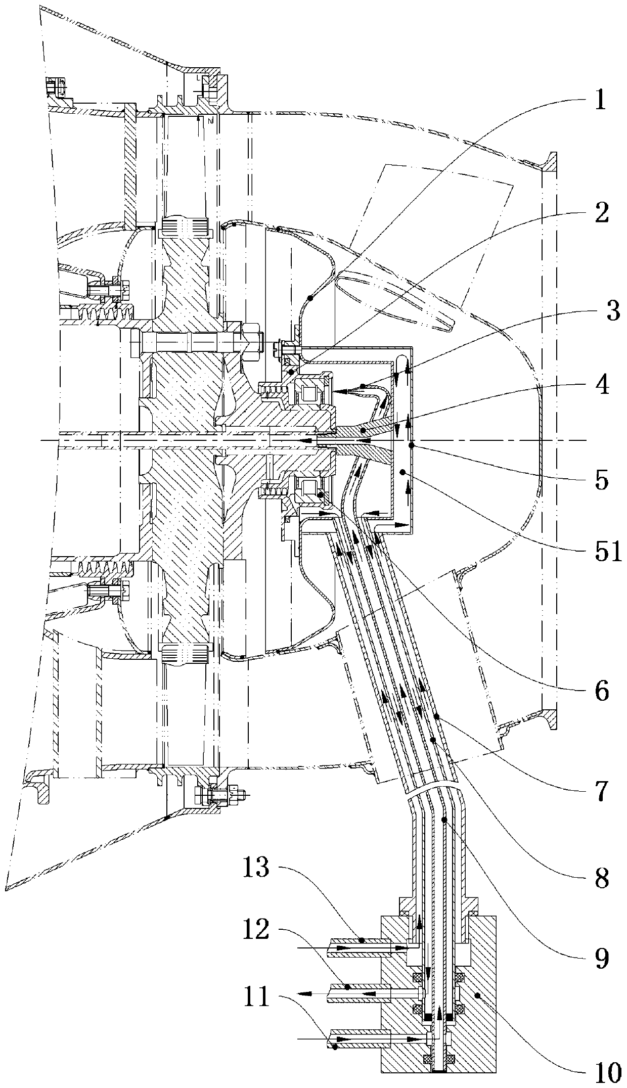
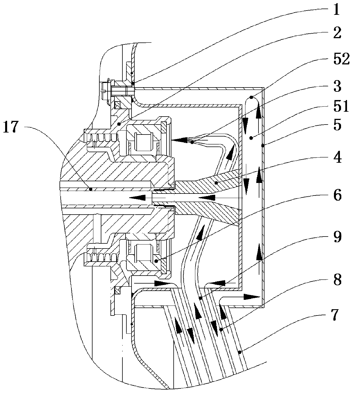
[0031]Such as Figure 1-5 As shown, a turbine engine hot end combustion oil pipeline structure includes a bearing 6, a bearing seat 2 is installed on the bearing 6, a lubricating oil return chamber housing 1 is installed on the bearing housing 2, and the lubricating oil return chamber housing 1 is wrapped with a fuel preheating chamber casing 5, and a fuel preheating chamber 51 is formed between the fuel preheating chamber casing 5 and the lubricating oil return chamber casing 1; it also includes nesting from the outside to the inside and leaving a gap between them One end of the fuel inlet pipe 7 communicates with the fuel preheating chamber 51, the fuel preheating chamber 51 communicates with the oil supply pipe 17, and the lubricating oil return pipe 8 One end communicates with the inside of the lubricating oil return chamber housing 1 , and one end of the lubricating oil inlet pipe 9 is located inside the lubricating oil return chamber housing 1 and opposite to the upper p...

Embodiment 2

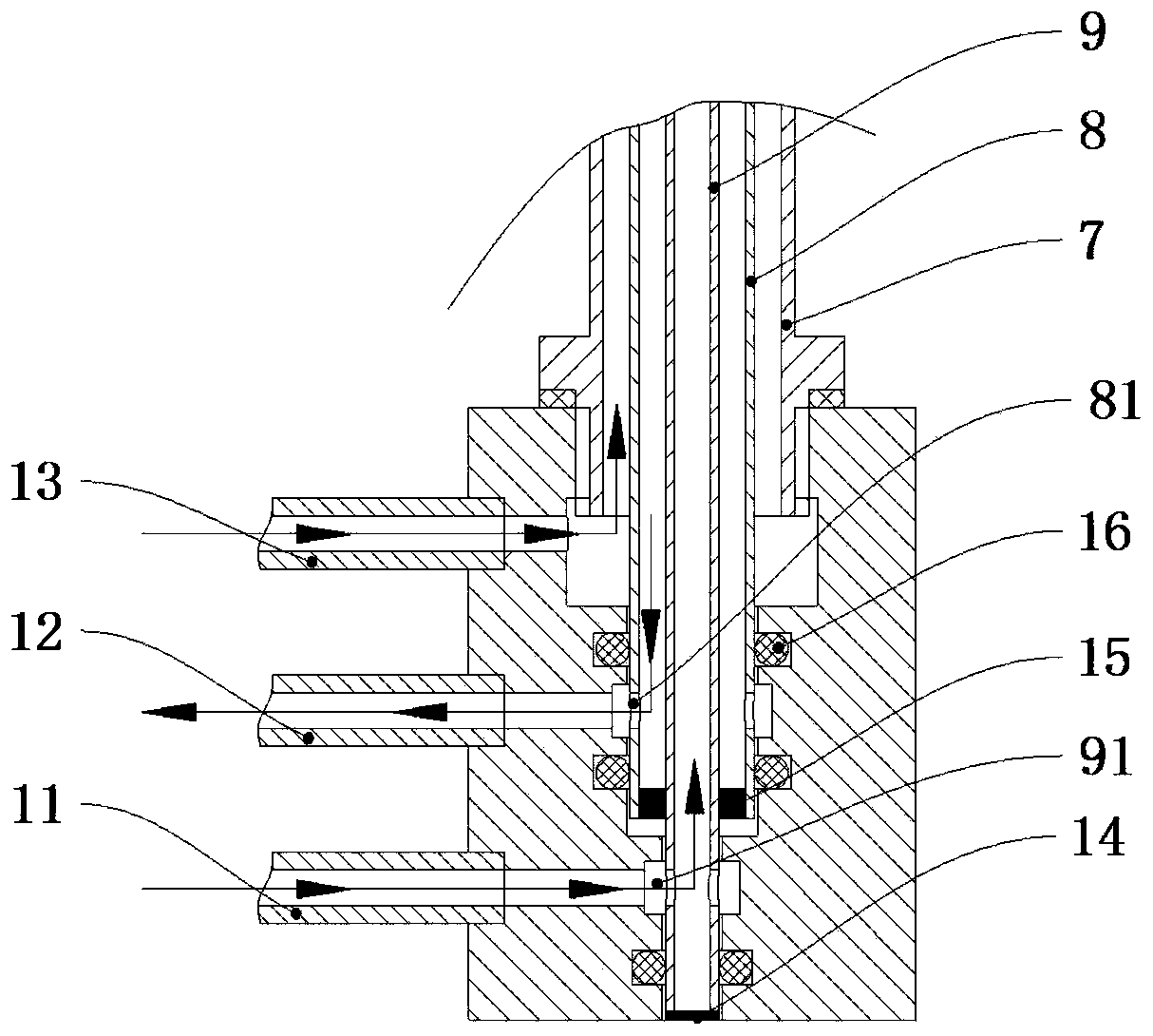
[0035] Such as Figure 1-5 As shown, on the basis of the above embodiments, this embodiment provides a preferred mechanism for connecting the fuel oil inlet pipe, the lubricating oil return pipe and the other end of the lubricating oil inlet pipe. That is, the other ends of the fuel inlet pipe 7, the lubricating oil return pipe 8 and the lubricating oil inlet pipe 9 are connected to the same pipe adapter 10, and the pipe adapter 10 is sequentially installed with a fuel oil inlet joint 13 and a lubricating oil outlet joint 12 , oil inlet joint 11, fuel oil inlet joint 13, oil outlet joint 12, oil inlet joint 11 are communicated with fuel oil inlet pipe 7, oil return pipe 8 and oil inlet pipe 9 successively.

[0036] Preferably, the middle part of the pipeline adapter 10 is sequentially provided with a fuel pipe connection hole 107, a lubricating oil return pipe connection hole 108 and a lubricating oil inlet pipe connection hole 109 from top to bottom, the fuel oil inlet pipe 7...


PUM


Abstract

The invention relates to the technical field of turbine engines, in particular to a hot end fuel and lubricating oil pipeline structure of a turbine engine, and aims to solve the problems that in theprior art, the heat efficiency of the engine cannot be better improved and a better cooling effect on a bearing cannot be achieved. The hot end fuel and lubricating oil pipeline structure comprises alubricating oil return cavity shell, a fuel oil preheating cavity shell, a fuel oil preheating cavity, a fuel oil inlet pipe, a lubricating oil return pipe and a lubricating oil inlet pipe, wherein the fuel oil inlet pipe, the lubricating oil return pipe and the lubricating oil inlet pipe are sequentially nested from outside to inside and are reserved with gaps among one another; one end of the fuel oil inlet pipe sequentially communicates with the fuel oil preheating cavity and a fuel oil supply pipe; one end of the lubricating oil return pipe communicates with the inside of the lubricating oil return cavity shell; and one end of the lubricating oil inlet pipe is positioned inside the lubricating oil return cavity shell and is opposite to the upper part of the bearing. According to the hot end fuel and lubricating oil pipeline structure, the fuel oil inlet pipe, the lubricating oil return pipe and the lubricating oil inlet pipe are sequentially nested from outside to inside, and the temperatures of the fluids in the three pipelines are sequentially reduced from outside to inside, so that the cooling effect on the bearing is improved and the heat efficiency of the engine is improved.

Description

technical field [0001] The invention relates to the technical field of turbine engines, and more particularly relates to a structure of a hot end combustion lubricating oil pipeline of a turbine engine. Background technique [0002] The bearings at the turbine end of the engine need to be cooled and lubricated by spraying lubricating oil. After the lubricating oil enters the bearing, it must pass through the high-temperature area of ​​the engine. On the one hand, when the lubricating oil flows through this area, it will exchange heat with the environment to increase the temperature of the lubricating oil sprayed on the bearing, thereby reducing the lubricating oil. The temperature difference between the oil and the bearing makes the cooling effect worse and the working temperature of the bearing rises. On the other hand, the temperature of the lubricating oil close to the wall of the oil supply pipeline is high, which is prone to coking of the lubricating oil, and the cokin...

Claims


Application Information

Patent Timeline
Patent Type & Authority Applications(China)
IPC IPC(8): F01D25/18F01D25/16F01D25/12F01D25/10
CPCF01D25/18F01D25/16F01D25/125F01D25/12F01D25/10
Inventor 熊杰刘驰欧阳兴宏宋勇刘焱敖
Owner SICHUAN AEROSPACE ZHONGTIAN POWER EQUIP CO LTD
Why Eureka
Try Eureka