Switched reluctance motor detection system and control method thereof
What is Al technical title?
Al technical title is built by PatSnap Al team. It summarizes the technical point description of the patent document.
A switched reluctance motor and detection system technology, applied in the direction of motor control, control system, radiation pyrometry, etc., can solve the problems of motor heating three-phase, imbalance, etc., to avoid fire, reduce maintenance costs, and protect power consumption The effect of equipment
Active Publication Date: 2020-02-21
成都智创利源科技有限公司
View PDF10 Cites 4 Cited by
Summary
Abstract
Description
Claims
Application Information
AI Technical Summary
This helps you quickly interpret patents by identifying the three key elements:
Problems solved by technology
Method used
Benefits of technology
Problems solved by technology
[0005] The technical problem to be solved by the present invention is to provide a switched reluctance motor detection system and control method, which can solve the problems of local heating and three-phase imbalance of the motor, realize closed-loop control of the internal temperature of the motor, and make the whole system work at the optimum level. Excellent running condition, high reliability, strong economy, easy operation and maintenance, greatly prolonging the life of the motor
Method used
Image
Click on the blue label to locate the original text in one second.
Reading with bidirectional positioning of images and text.
Examples
Embodiment Construction
[0037] The present invention will be further described in detail below in conjunction with the accompanying drawings and specific embodiments.
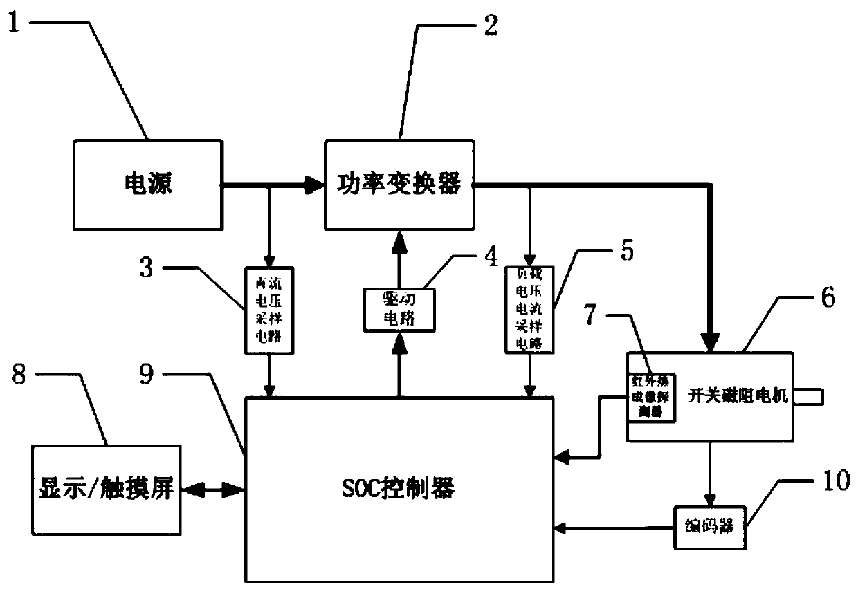
[0038] Such as figure 1 As shown, the detection of the switched reluctance motor in the present invention includes a power supply 1, a power converter 2, an infrared thermal imaging detector 7, an encoder 10, an SOC controller 9, a drive circuit 4, a DC voltage sampling circuit 3, and a load voltage and current sampling circuit. The circuit 5 and the display / touch screen 8 are composed. The power supply 1 is connected to the power converter 2 to supply power for the power converter 2; the SOC controller 9 is connected to the power converter 2 for driving the switched reluctance motor 6 through the drive circuit 4; the SOC controller 9 also The DC voltage sampling circuit 3, the load voltage and current sampling circuit 5, the infrared thermal imaging detector 7, the encoder 10 and the display / touch screen 8 are respectively connecte...
PUM
Abstract
The invention, which belongs to the field of motor control, discloses a switched reluctance motor detection system and a control method thereof. The detection system comprises a power supply, a powerconverter, an infrared thermal imaging detector, an encoder, an SOC controller, a drive circuit, a sampling circuit and a display / touch screen. When a switched reluctance motor is in normal operation,the detection system uses the infrared thermal imaging detector to monitor the temperature of each component in the motor in real time; when the internal temperature of the motor is detected to exceed a limit or to be abnormal, the shutdown operation is carried out in time or the running state of the motor is changed in time, so that faults are cut off timely and conveniently and the motor reaches an optimal running state effect. Meanwhile, the infrared thermal imaging detector and the switched reluctance motor are controlled in a unified mode to realize closed-loop control over the internaltemperature of the motor, so that the whole system is made to work in the optimal operation state. The system has advantages of high reliability, high economy, and great convenient in operation and maintenance.
Description
technical field [0001] The invention belongs to the field of motor control, in particular to a detection system and a control method of a switched reluctance motor. Background technique [0002] Switched reluctance motors have the advantages of simple and solid structure, low cost, etc., suitable for high-speed, variable load operation, and are widely used in aviation industry, electric vehicles, pumping units, household appliances and other fields. During the operation of the switched reluctance motor, due to the existence of high room temperature, poor heat dissipation, overload, overvoltage, undervoltage or voltage imbalance, frequent start and stop or frequent forward and reverse rotation, lack of phase, broken fan or blocked air inlet and outlet, and lack of bearing Oil, mechanical jamming and stalling, excessive load moment of inertia, long start-up time, short circuit between turns, incorrect internal wiring of the new motor, damp motor, rotor sweeping, excessive powe...
Claims
Application Information
Patent Timeline
Application Date:The date an application was filed.
Publication Date:The date a patent or application was officially published.
First Publication Date:The earliest publication date of a patent with the same application number.
Issue Date:Publication date of the patent grant document.
PCT Entry Date:The Entry date of PCT National Phase.
Estimated Expiry Date:The statutory expiry date of a patent right according to the Patent Law, and it is the longest term of protection that the patent right can achieve without the termination of the patent right due to other reasons(Term extension factor has been taken into account ).
Invalid Date:Actual expiry date is based on effective date or publication date of legal transaction data of invalid patent.