
Detection method for illumination uniformity of photo-etching machine

A technology of illumination uniformity and detection method, which is applied in the field of lithography machines, can solve the problems of inability to detect in real time, time-consuming, low efficiency, etc., and achieve the effects of low cost, improved accuracy, and improved detection efficiency

Pending Publication Date: 2020-02-21
ZHUHAI MULTISCALE PHOTOELECTRIC TECH CO LTD
View PDF0 Cites 0 Cited by
  • Summary
  • Abstract
  • Description
  • Claims
  • Application Information

AI Technical Summary

Problems solved by technology

This method is time-consuming and cannot detect in real time
When using this method, every part of the optical system needs to re-measure the uniformity of illumination after adjustment, which is inefficient

Method used


Image

  • Detection method for illumination uniformity of photo-etching machine
  • Detection method for illumination uniformity of photo-etching machine
  • Detection method for illumination uniformity of photo-etching machine

Examples


Embodiment approach

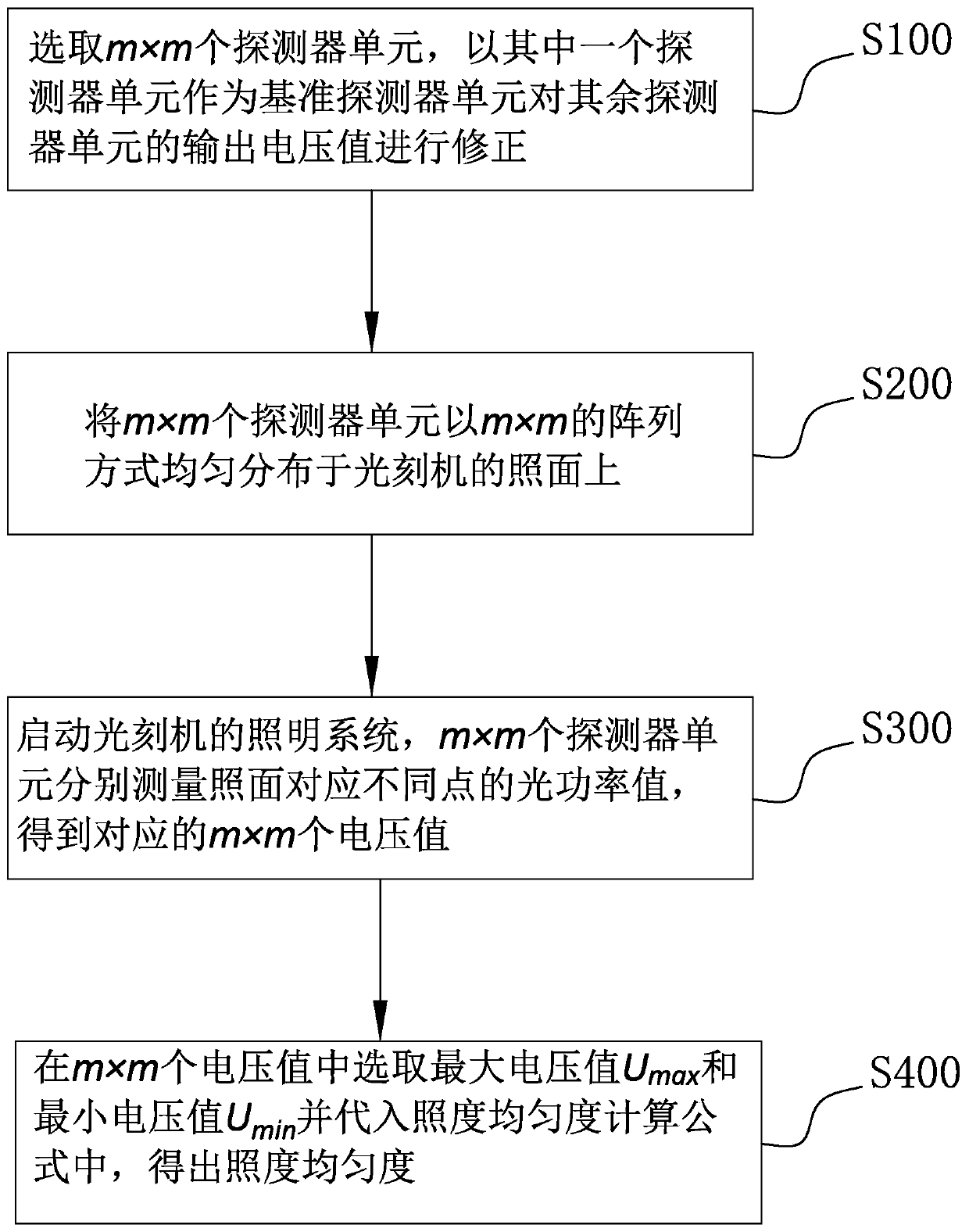
[0035] refer to figure 1 , which is a preferred embodiment, a method for detecting the uniformity of illuminance of a photolithography machine, comprising:

[0036] S100. Select m×m detector units, and use one of the detector units as a reference detector unit to correct the output voltage values ​​of the remaining detector units;

[0037] S200, evenly distributing m×m detector units on the illumination surface of the lithography machine in an m×m array;

[0038] S300. Start the lighting system of the lithography machine, and measure the optical power values ​​corresponding to different points on the illuminated surface with m×m detector units to obtain corresponding m×m voltage values;

[0039] S400. Select the maximum voltage value U from the m×m voltage values max and the minimum voltage value U min And substituting it into the calculation formula of illuminance uniformity, the illuminance uniformity of the photolithography machine under the current optical power value i...

Embodiment 1

[0064] Embodiment 1, the size of the photolithography machine is 32 inches, and 3×3 detector units are used:

[0065] First of all, for the convenience of distinction, the nine detector units are recorded as the first detector unit, the second detector unit, the third detector unit, the fourth detector unit, the fifth detector unit, and the sixth detector unit , the seventh detector unit, the eighth detector unit and the ninth detector unit.

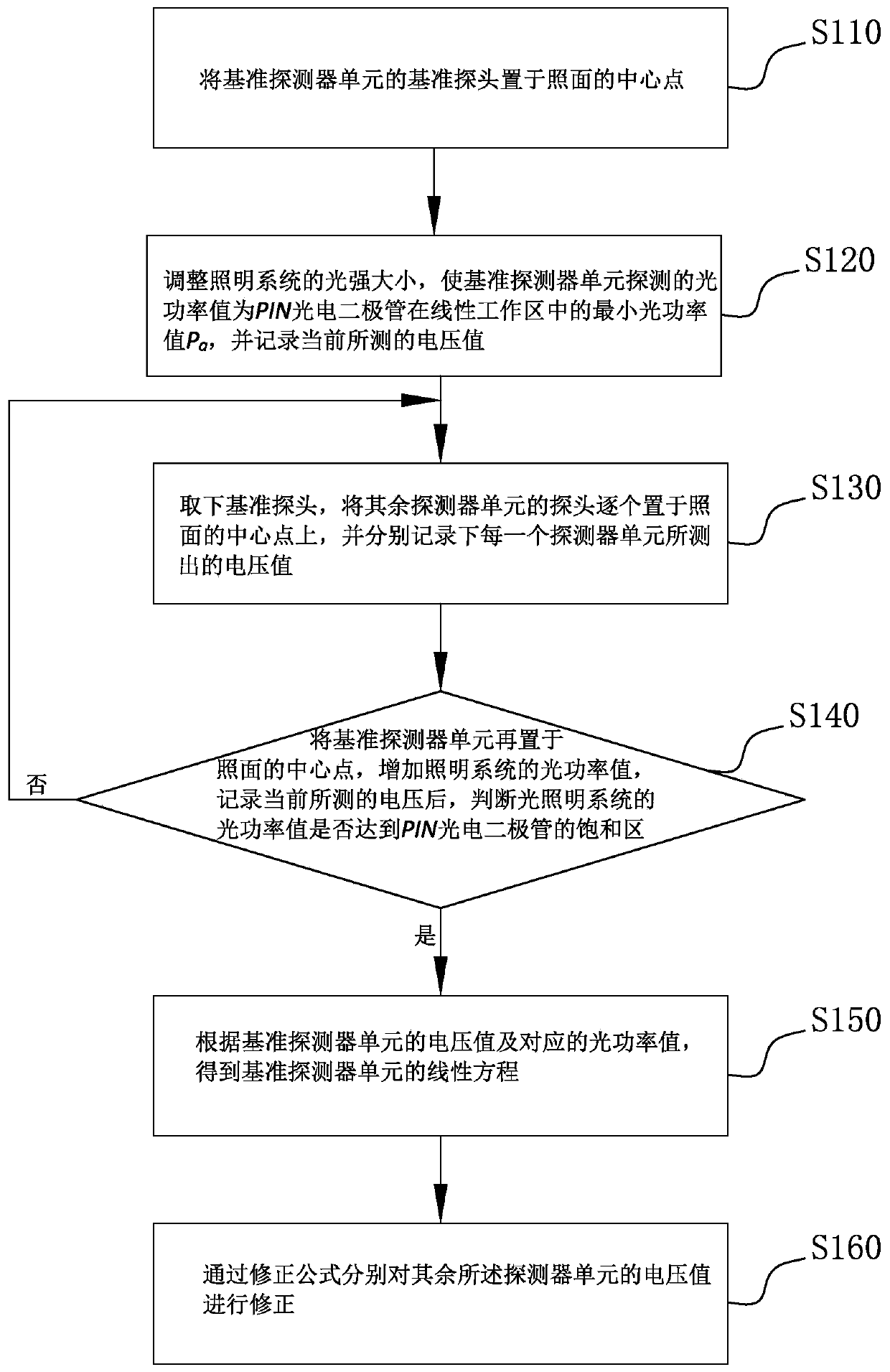
[0066] First, one of the detector units is selected as the reference detector unit, in this embodiment, the first detector unit is selected as the reference detector unit, and then the correction is performed according to steps S110 to S160, then the first detector unit can be obtained Linear equations, and get the correction formulas of the second to ninth detector units respectively.

[0067] Among them, according to the voltage value measured by the first detector and the corresponding optical power value, it can be obtained that the...


PUM


Abstract

The invention relates to the technical field of photo-etching machines, and discloses a detection method for the illumination uniformity of a photo-etching machine, which can be used to rapidly and accurately detect the illumination uniformity of an illuminated surface. The method comprises the following steps: S100, selecting m*m detector units, and correcting output voltage values of other detector units by taking one detector unit as a reference detector unit; S200, uniformly distributing the m*m detector units on the illuminated surface of the photo-etching machine in an m*m array manner;S300, starting an illumination system of the photo-etching machine, and respectively measuring optical power values of different points corresponding to the illuminated surface by the m*m detector units to obtain corresponding m*m voltage values; and S400, selecting a maximum voltage value Umax and a minimum voltage value Umin from the m*m voltage values, and substituting the maximum voltage valueUmax and the minimum voltage value Umin into an illumination uniformity calculation formula to obtain the illumination uniformity under the current optical power value. The detection efficiency is improved through an array type detection method. Meanwhile, the detector units are corrected in a unified mode, and the accuracy of the detection result is improved.

Description

technical field [0001] The invention relates to the technical field of lithography machines, in particular to a method for detecting the uniformity of illumination of a lithography machine. Background technique [0002] At present, in order to measure the uniformity of the illumination surface of the light source of the lithography machine, the usual method is to place a single probe in the illumination surface for point-by-point measurement. Specifically, using a single probe optical power meter, the multi-point measurement method is used to measure the light intensity of the corresponding points block by block in the illuminated surface, and the illumination uniformity of the illuminated surface of the lithography machine is calculated. This method is time-consuming and cannot be detected in real time. When this method is adopted, each part of the optical system needs to be re-measured for illumination uniformity after adjustment, which is inefficient. Contents of the i...

Claims


Application Information

Patent Timeline
Patent Type & Authority Applications(China)
IPC IPC(8): G03F7/20
CPCG03F7/70075G03F7/7055
Inventor 王乡
Owner ZHUHAI MULTISCALE PHOTOELECTRIC TECH CO LTD
Learn More