Outdoor totally-enclosed composite insulation three-phase combined mutual inductor

A combined transformer and composite insulation technology, applied in the field of transformers, can solve problems such as increased labor and equipment costs, difficulty in professional recycling, and low volatility, so as to reduce the workload of inspection and maintenance, and facilitate daily maintenance. The effect of structural fit

Active Publication Date: 2020-02-21
湖南大北互互感器有限公司 +1
View PDF10 Cites 1 Cited by
  • Summary
  • Abstract
  • Description
  • Claims
  • Application Information

AI Technical Summary

Problems solved by technology

[0002] At present, there are few three-phase outdoor combined transformers with a rated voltage of 15-20kV for domestic power system applications, and their product technology is not mature enough to adapt to Use in areas above 3000 meters above sea level
For example, patent 201811637129.8 discloses a three-phase four-wire combined transformer. This product adopts the technical scheme of combining three independent current transformers and one voltage transformer. According to the analysis, there are the following problems: the structure of the whole machine is complex, and such Huge combined structure, once the equipment is damaged or fails, all the transformers need to be removed for maintenance and replacement, which brings inconvenience to daily maintenance and repair, and greatly increases the cost of labor and equipment
Moreover, the sealing performance and anti-interference ability of the whole machine are poor, resulting in low mechanical strength, which is not conducive to the complex and changeable outdoor operating environment
In addition, this product adds SF6 and other gases to the current transformer. This type of gas is more harmful, prone to leakage, and has a shorter service life. Once leaked, it is not easy to volatilize. Therefore, regular maintenance is required, which will also greatly increase the work. Volume and cost, professional recycling is difficult to achieve

Method used


Image

  • Outdoor totally-enclosed composite insulation three-phase combined mutual inductor
  • Outdoor totally-enclosed composite insulation three-phase combined mutual inductor
  • Outdoor totally-enclosed composite insulation three-phase combined mutual inductor

Examples


Embodiment Construction

[0035] Below in conjunction with accompanying drawing, the specific embodiment of the present invention is described in detail as follows:

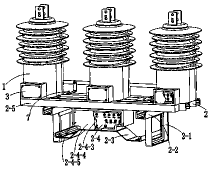
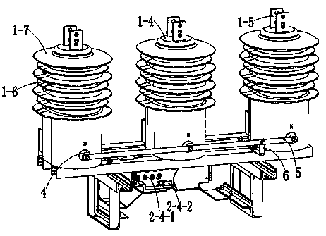
[0036] see Figure 1-5 , an outdoor fully enclosed composite insulated three-phase combined transformer, including three single-phase combined transformers 1 with the same structure and a base 2, two frame-type support frames 2-1 are installed on the lower part of the base 2, each supporting Mounting holes are provided on the frame at the bottom of the frame 2-1, a fixing frame 2-2 is installed between the supporting frame 2-1 and the base 2, and mounting holes are provided at both ends of the fixing frame 2-2. A bridge support frame 2-3 is installed through bolts between the two support frames 2-1, a terminal box 2-4 is arranged on the bridge support frame 2-3, and a wire inlet hole is reserved on the top of the terminal box 2-4 , one side of the fixed frame 2-2 is provided with a cable tube 2-5, and the upper and lower ends of the cabl...


PUM


Abstract

The invention discloses an outdoor totally-enclosed composite insulation three-phase combined transformer. The transformer comprises three single-phase combined transformers of the same structure anda base, the three single-phase combined transformers are arranged to be a phase A, a phase B and a phase C respectively and evenly arranged on the base, and a junction box and a low-voltage terminal of a high-voltage primary coil are correspondingly arranged on the two sides of the lower portion of each single-phase combined transformer; the low-voltage terminals of the three single-phase combinedtransformers are connected through a line bank, the line bank is connected with a grounding terminal strip, and the grounding terminal strip is connected with a grounding terminal on the base. The three-phase combined transformer is compact in structure, excellent in layout, accurate in metering and stable and reliable in performance, the outdoor complex operation environment is fully considered,the current part can achieve three transformation ratios, the voltage part can achieve voltage conversion from 15 kV to 20 kV according to different requirements of users, installation is convenient,pollution flashover resistance is achieved, maintenance is avoided, the self-cleaning performance is high, electricity larceny prevention is reliable, and the operation life is long.

Description

technical field [0001] The invention relates to a transformer, in particular to a 15-20kV outdoor fully enclosed composite insulated three-phase combined transformer. Background technique [0002] At present, there are few three-phase outdoor combined transformers with a rated voltage of 15-20kV for domestic power system applications, and their product technology is not mature enough to be suitable for use in areas above 3000 meters above sea level. For example, patent 201811637129.8 discloses a three-phase four-wire combined transformer. This product adopts the technical scheme of combining three independent current transformers and one voltage transformer. According to the analysis, there are the following problems: the structure of the whole machine is complex, and such The huge combined structure, once the equipment is damaged or fails, all the transformers need to be removed before maintenance and replacement, which brings inconvenience to daily maintenance and overhaul...

Claims


Application Information

Patent Timeline
Patent Type & Authority Applications(China)
IPC IPC(8): H01F27/02H01F27/04H01F27/06H01F27/29H01F38/38
CPCH01F27/022H01F27/04H01F27/06H01F27/29H01F38/38
Inventor 郝桃武郭胜潘瑜朱成璋杨智茂万慧英孙艳李润芳胡蓉刘歌
Owner 湖南大北互互感器有限公司
Why Eureka
Try Eureka