Outdoor switch cabinet

A switchgear, outdoor technology, applied in the field of switchgear, can solve the problems of normal operation damage of electronic components inside the cabinet, damage of electronic components inside the cabinet, influence of the operation of electronic components, etc., to ensure the filtering performance and improve the use. The effect of lifespan and the reduction of the probability of destruction

Pending Publication Date: 2020-02-21
雷朋电气集团有限公司
View PDF0 Cites 1 Cited by
  • Summary
  • Abstract
  • Description
  • Claims
  • Application Information

AI Technical Summary

Problems solved by technology

[0002] Switchgear is a kind of electrical equipment. Its main function is to open and close, control and protect electrical equipment during the process of power generation, transmission, distribution and power conversion in the power system. When the switchgear is in use, its internal electronic components It will generate heat, and if the generated heat is not discharged in time, it may affect the operation of the electronic components inside the cabinet. The switch cabinet is generally located outdoors, and the terrain of the switch cabinet is low, and water collection may occur when it rains. The water collection in the area where the switchgear is located may cause the water to enter the cabinet, thereby causing damage to the electronic components inside the cabinet. When the switchgear is installed outdoors, there are high requirements for its rainproof performance. Inside, it will cause damage to the electronic components inside the cabinet. The switchgear usually has cooling holes for the convenience of heat dissipation. The opening of the cooling holes will allow dust, tiny insects, etc. The operation causes damage, and the existing switchgear has a single function, which can no longer meet the multifunctional needs of the switchgear in today's society, so a new solution is now needed

Method used


Image

  • Outdoor switch cabinet
  • Outdoor switch cabinet
  • Outdoor switch cabinet

Examples


Embodiment 1

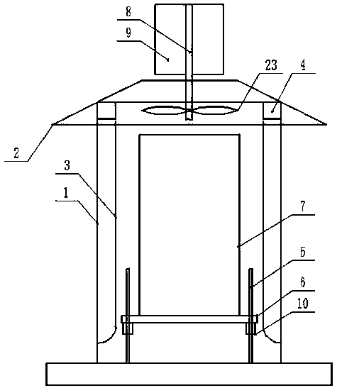
[0014] Embodiment 1: see figure 1 , figure 2 , image 3 , Figure 4 Now, an outdoor switch cabinet provided by the present invention is described, including a cabinet body 1 and a rainproof housing 2 provided on the top of the cabinet body 1, and the inner ends of the left and right sides of the cabinet body 1 are respectively provided with rainproof frames. 3. The top, left, and right sides of the cabinet body 1 are respectively provided with air guiding shells 4, and the inner bottom end of the cabinet body 1 is uniformly and vertically provided with positioning support shafts 5, and the inner bottom end of the cabinet body 1 is provided with Some support bases 6, the upper end of the support base 6 is provided with a protective shell 7, the middle part of the outer top of the cabinet 1 is vertically provided with a transmission shaft 8, and the outside of the transmission shaft 8 is evenly and vertically provided with a guide Flow rack9.

Embodiment 2

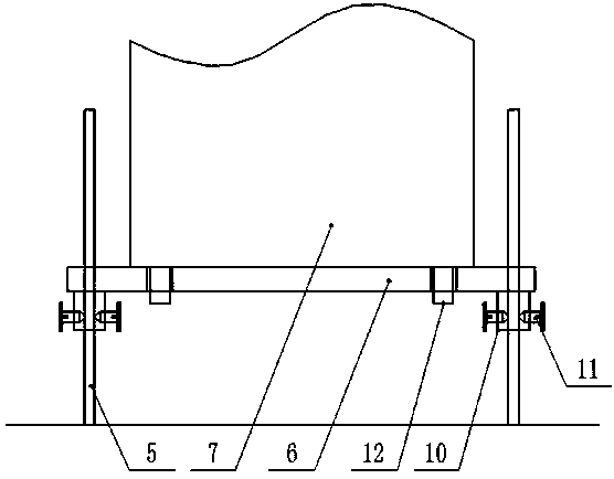
[0015] Example 2: see figure 1 , figure 2 Now, an outdoor switch cabinet provided by the present invention is described. The horizontal cross-section of the cabinet body 1 is rectangular, the number of the positioning support shafts 5 is four, the support base 6 is a rectangular plate, and the four corners of the support base 6 are There are circular openings at the ends respectively, and the positioning support shafts 5 are arranged to move vertically through the circular openings respectively. The lower end of the support base 6 and the positions corresponding to the circular openings are respectively provided with cylindrical fastening frames 10, so that The diameter of the inner port of the cylindrical fastening frame 10 is equal to the diameter of the internal port of the circular port, and the non-connecting ends of the cylindrical fastening frame 10 are uniformly provided with fastening screw holes in equal arcs. Set screws 11 are respectively screwed into the holes, ...

Embodiment 3

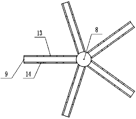
[0016] Embodiment 3: see figure 1 , image 3 , Figure 4, an outdoor switchgear provided by the present invention will now be described. The rainproof housing 2 is set as a hollow truncated prism, and its lower end opening has no end plate design, and the bottom end of the transmission shaft 8 in the vertical direction is movable into In the inner cavity of the top of the cabinet body 1, the top end moves through the top wall of the rainproof housing 2, and the guide frame 9 is evenly and vertically arranged on the outside of the top extension end of the transmission shaft 8, Solar panels 13 and reflectors 14 are vertically interspersed on the end walls on both sides of the guide frame 9 in the thickness direction, and the lower end of the wind guide housing 4 and the horizontally corresponding ends are respectively provided with openings. The inner side of the lower port of the air guide housing 4 is respectively provided with a filter screen 15, the inner side of the corre...


PUM


Abstract

The invention discloses an outdoor switch cabinet. The cabinet comprises a cabinet body and a rainproof shell arranged at a top of the cabinet body. Rainproof frame bodies are arranged at inner ends of a left side and a right side of the cabinet body correspondingly. The left side and the right side of a top end in the cabinet body are provided with air guide shells. Positioning supporting shaftsare evenly and vertically arranged at an inner bottom end of the cabinet body, a supporting pedestal is arranged at the inner bottom end of the cabinet body, a protective shell is arranged at an upperend of the supporting pedestal, a transmission shaft is vertically arranged in the middle of an outer top end of the cabinet body, and flow guide frames are evenly and vertically arranged outside thetransmission shaft at equal radians.

Description

technical field [0001] The invention relates to the field of switch cabinets, in particular to an outdoor switch cabinet. Background technique [0002] Switchgear is a kind of electrical equipment. Its main function is to open and close, control and protect electrical equipment during the process of power generation, transmission, distribution and power conversion in the power system. When the switchgear is in use, its internal electronic components It will generate heat, and if the generated heat is not discharged in time, it may affect the operation of the electronic components inside the cabinet. The switch cabinet is generally located outdoors, and the terrain of the switch cabinet is low, and water collection may occur when it rains. The water collection in the area where the switchgear is located may cause the water to enter the cabinet, thereby causing damage to the electronic components inside the cabinet. When the switchgear is installed outdoors, there are high req...

Claims


Application Information

Patent Timeline
Patent Type & Authority Applications(China)
IPC IPC(8): H02B1/30H02B1/56H02B1/28
CPCH02B1/28H02B1/303H02B1/565
Inventor 钟新国耿昌鹏
Owner 雷朋电气集团有限公司
Why Eureka
Try Eureka