
Synchronous rectification control method for successive adjustment of gate, controller and switching power supply

A technology of synchronous rectification and control method, applied in the direction of regulating electrical variables, control/regulating systems, instruments, etc., can solve the problem of increasing energy loss and achieve the effect of low energy loss

Active Publication Date: 2020-02-21
HUAYUAN SEMICON SHENZHEN LTD
View PDF9 Cites 0 Cited by
  • Summary
  • Abstract
  • Description
  • Claims
  • Application Information

AI Technical Summary

Problems solved by technology

In order to avoid a short circuit, it is difficult to set the first threshold to a small value, which will increase the energy loss

Method used


Image

  • Synchronous rectification control method for successive adjustment of gate, controller and switching power supply
  • Synchronous rectification control method for successive adjustment of gate, controller and switching power supply
  • Synchronous rectification control method for successive adjustment of gate, controller and switching power supply

Examples


no. 1 example

[0040] The present embodiment provides a synchronous rectification control method for successive gate adjustments. This control method is used to control the rectifying transistor in the conversion circuit 100 .

[0041] The conversion circuit 100 is used to convert electric energy; in this embodiment, the conversion circuit 100 is an AC-DC conversion circuit, which can convert AC power into DC power; in other embodiments, the conversion circuit 100 is a DC-DC conversion circuit.

[0042] refer to Figure 5 , the conversion circuit 100 includes a rectifier transistor 1 and an inductor winding 2 . In this embodiment, the inductor winding 2 is the secondary winding of the transformer; the rectifying transistor 1 is a MOSFET transistor; in other embodiments, the rectifying transistor 1 can be selected from other transistors with rectifying function. The rectifier transistor 1 has a gate G, a source S and a drain D. As shown in FIG. The source G and the drain D can provide a ch...

no. 2 example

[0079] This embodiment provides a switching power supply. The switching power supply includes the aforementioned synchronous rectification controller 200 . Wherein, the synchronous rectification controller 200 is used in the above synchronous rectification control method of this embodiment.

[0080] Those skilled in the art can understand that all or part of the process in the method of the embodiment can be completed by a computer program to instruct the relevant hardware, the program can be stored in a computer-readable storage medium, and when the program is executed, it can include various methods. example process. The aforementioned storage medium includes: ROM or random access memory RAM, magnetic disk or optical disk, and other various media that can store program codes.


PUM


Abstract

The invention discloses a synchronous rectification control method for successive adjustment of a gate, a controller and a switching power supply. The method comprises the following steps: outputtinga modulation signal to gradually reduce the gate voltage of a rectifier transistor; comparing the drain voltage of the rectifier transistor with a first threshold voltage and outputting a modulation signal; comparing the drain voltage of the rectifier transistor with a second threshold voltage and outputting a gate turn-off signal; calculating a time t<reg> from the output of the modulation signalto the turn-off of the rectifier transistor; comparing the time t<reg> with a reference time t<ref>; if the time t<reg> is longer than the reference time t<ref>, outputting a next modulation signal to shorten a next time t<reg>; and if the time t<reg> is shorter than the reference time t<ref>, outputting a next modulation signal to prolong a next time t<reg>. The controller may perform the method. The switching power supply comprises the controller. According to the invention, the energy loss can be minimized, and the zero crossing point can be accurately detected.

Description

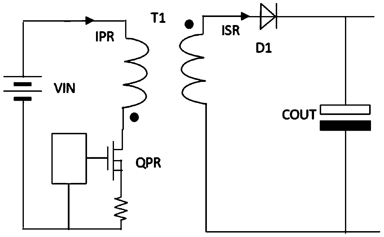
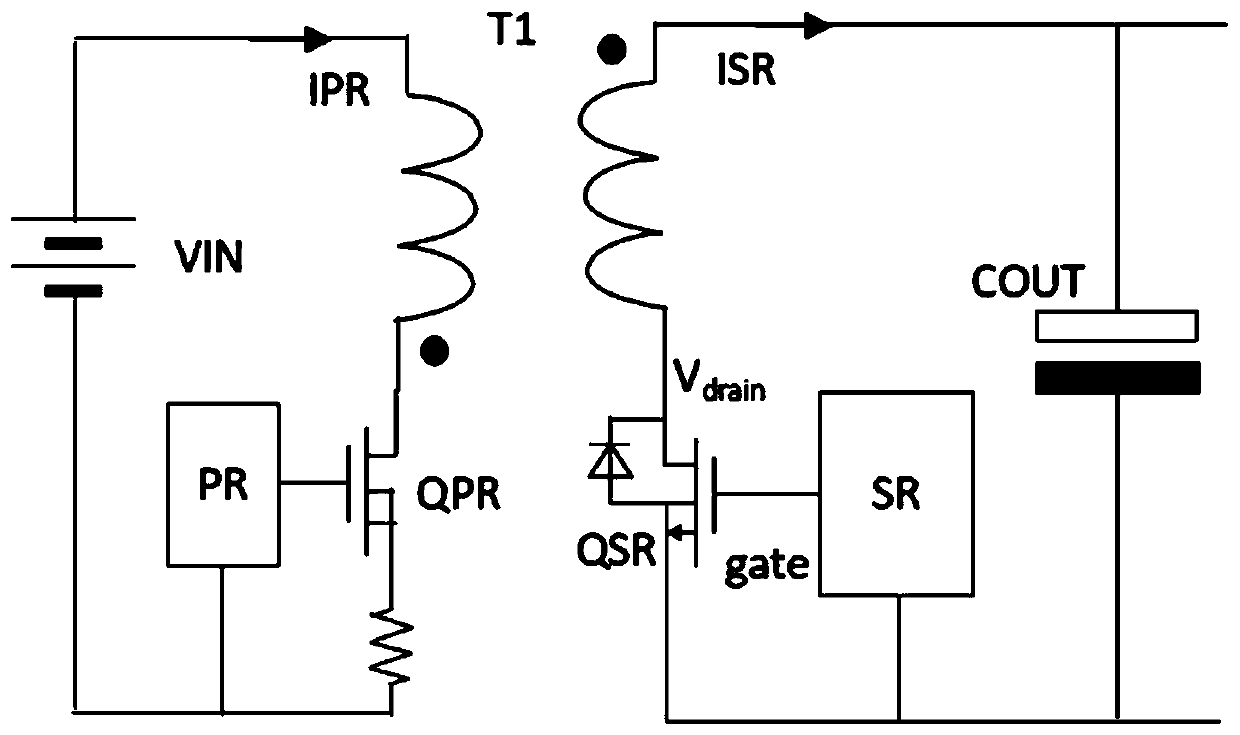
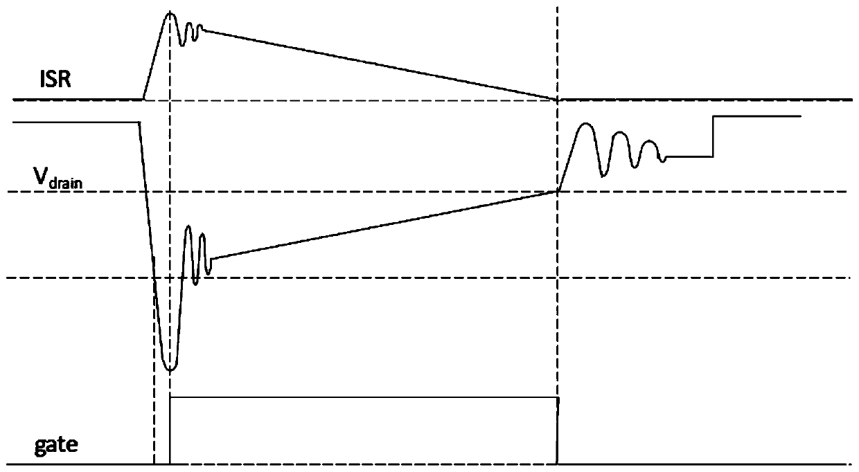
technical field [0001] The present application relates to the technical field of switching power supplies, and in particular to a synchronous rectification control method with sequential gate adjustment, a controller and a switching power supply. Background technique [0002] Rectifier diodes are used in switching converters such as flyback and buck converters, both of which are used to provide a DC voltage output. figure 1 A flyback converter is shown that includes a transformer T1 consisting of a primary winding and a secondary winding. The source and drain of the MOSFET (Metal-Oxide-Semiconductor Field-Effect Transistor, Metal-Oxide Semiconductor Field-Effect Transistor) transistor are connected to the primary winding, and an input voltage source VIN controlled by the primary side controller is used as a switch . The secondary section consists of a diode D1 and the secondary winding, with the diode connected in series with the secondary winding. When the MOSFET transis...

Claims


Application Information

Patent Timeline
Patent Type & Authority Applications(China)
IPC IPC(8): H02M3/335H02M1/08
CPCH02M1/083H02M3/33592H02M1/0058Y02B70/10
Inventor 张程龙
Owner HUAYUAN SEMICON SHENZHEN LTD
Learn More