A digital lock-in amplifier phase synchronization method and system

A digital phase-locking and phase-synchronization technology, applied in automatic power control, electrical components, etc., can solve the problems of out-of-phase synchronization, few applicable scenarios, high cost, and high power consumption, so as to reduce power consumption and cost, and expand application scenarios Effect

Active Publication Date: 2022-03-01
UNIV OF SCI & TECH OF CHINA
View PDF5 Cites 0 Cited by
  • Summary
  • Abstract
  • Description
  • Claims
  • Application Information

AI Technical Summary

Problems solved by technology

One is to strictly control the transmission delay to ensure that the delays of the two are consistent. Since the carrier and the modulation signal at the signal modulation end are phase-synchronized, the phases of the two at the receiving end are also synchronized. This method often cannot strictly guarantee the delay in complex environments. Consistent, especially the delay of some devices in the transmission process is slowly changing, so this method is less suitable for scenarios
The other is that the receiving end directly outputs the carrier to drive the modulating end, so that the phase of the modulating end is directly controlled by the receiving end, so that the phases of both ends are unified to complete phase synchronization. The situation is difficult to apply, there are limitations
The third method is to directly generate a signal of the same frequency orthogonal to the reference carrier, and then use two orthogonal reference signals to perform two-way phase-locked amplification with the signal to be tested at the same time, so as to obtain the specific frequency component of the signal to be tested at two orthogonal The projection intensity in the cross-carrier direction, and then use triangulation to synthesize the final result. This method uses two lock-in amplifiers to realize the function of one lock-in amplifier, which solves the problem of phase asynchrony, but it takes up a lot of resources, cost, and high power consumption

Method used


Image

  • A digital lock-in amplifier phase synchronization method and system
  • A digital lock-in amplifier phase synchronization method and system
  • A digital lock-in amplifier phase synchronization method and system

Examples


Embodiment Construction

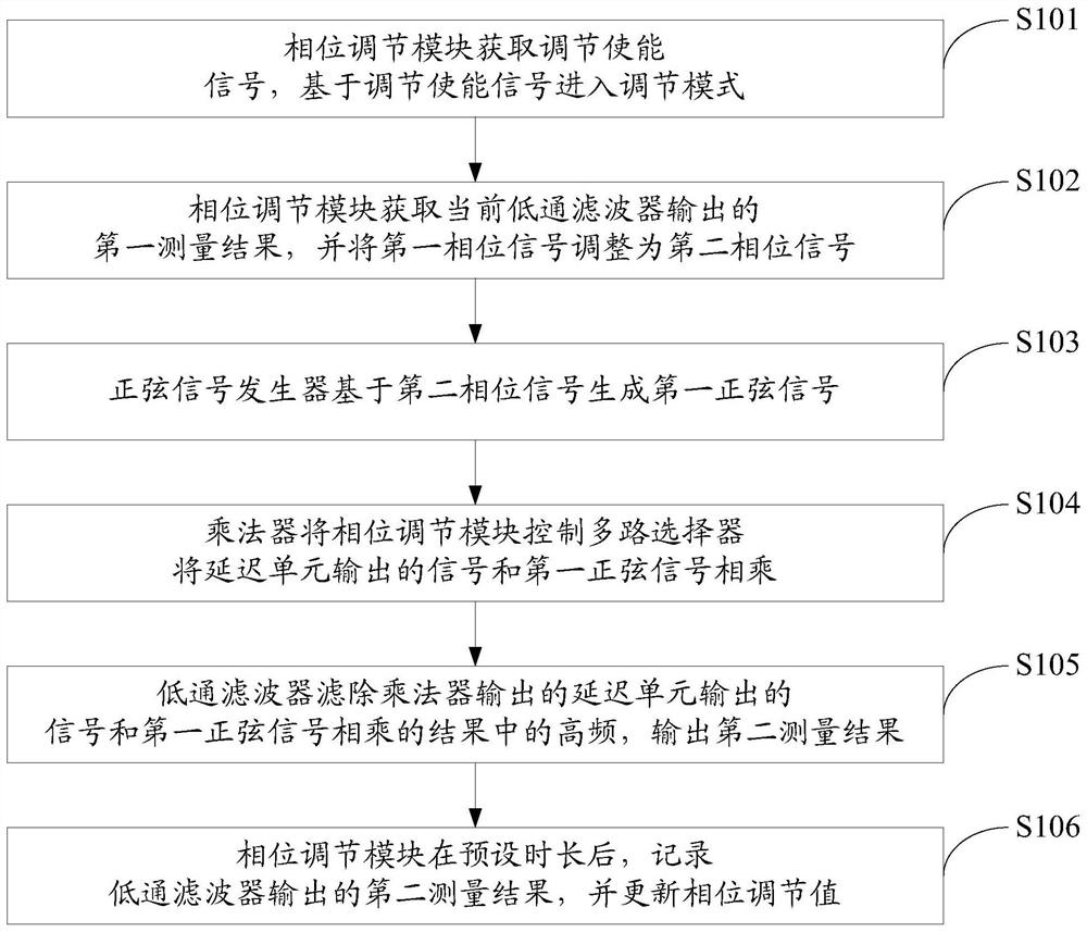
[0046] like figure 1 As shown, it is a method flowchart of Embodiment 1 of a digital lock-in amplifier phase synchronization method disclosed in the present application, and the method may include the following steps:

[0047] S101. The phase adjustment module acquires an adjustment enable signal, and enters an adjustment mode based on the adjustment enable signal;

[0048] When the phase between the signal to be measured and the reference signal of the digital lock-in amplifier needs to be synchronized, the phase adjustment module receives the adjustment enable signal, and the phase adjustment module enters an adjustment mode.

[0049] S102. The phase adjustment module acquires the first measurement result output by the current low-pass filter, and adjusts the first phase signal to a second phase signal;

[0050] When the phase adjustment module enters the adjustment mode, record the output value of the current low-pass filter, that is, obtain the measurement result of the c...


PUM


Abstract

The application discloses a method and system for phase synchronization of a digital lock-in amplifier. The method includes: the phase adjustment module obtains an adjustment enable signal, and enters an adjustment mode based on the adjustment enable signal; Measure the result, and adjust the first phase signal to the second phase signal; the sinusoidal signal generator generates the first sinusoidal signal based on the second phase signal; A sinusoidal signal is multiplied; the low-pass filter filters out the high frequency in the result of multiplying the signal output by the delay unit output by the multiplier and the first sinusoidal signal, and outputs the second measurement result; after a preset period of time, the phase adjustment module, A second measurement of the output of the low pass filter is recorded and the phase adjustment value is updated. The present application can effectively realize the phase synchronization of the digital lock-in amplifier and reduce resource consumption.

Description

technical field [0001] The present application relates to the technical field of digital lock-in amplifiers, in particular to a phase synchronization method and system for digital lock-in amplifiers. Background technique [0002] Lock-in Amplifier (LIA) is a technology widely used in measuring weak signals in larger noises, and has the advantage of strong anti-interference ability. In the magnetic confinement nuclear fusion plasma experiment, the laser dispersion interferometer requires high-precision phase-locked amplification. With the rapid development of digital technology, digital lock-in amplifiers have comprehensive advantages over analog lock-in amplifiers. When the digital lock-in amplifier is working, it is necessary to ensure the phase synchronization between the input signal and the reference carrier signal, otherwise the strength of the output signal will be weakened, and the measurement accuracy will be greatly reduced. [0003] At present, there are roughly ...

Claims


Application Information

Patent Timeline
Patent Type & Authority Patents(China)
IPC IPC(8): H03L7/093H03L7/085
CPCH03L7/093H03L7/085
Inventor 阴泽杰吴彤宇张伟徐修峰
Owner UNIV OF SCI & TECH OF CHINA
Why Eureka
Try Eureka