

Feed bin controlling discharging
A technology of feeding bins and moving seats, applied in the field of feeding bins, can solve the problems of insufficient functions, simplicity, and inability to control the amount and speed of feeding and lowering, and achieve the effect of simple structure and easy popularization and application
- Summary
- Abstract
- Description
- Claims
- Application Information
AI Technical Summary
Problems solved by technology
Method used
Image

Examples
Embodiment 1
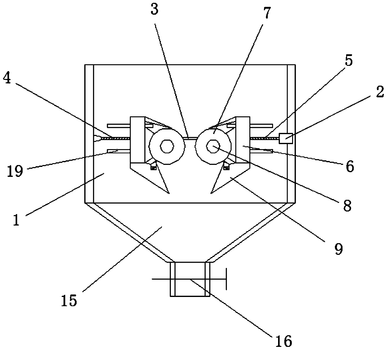
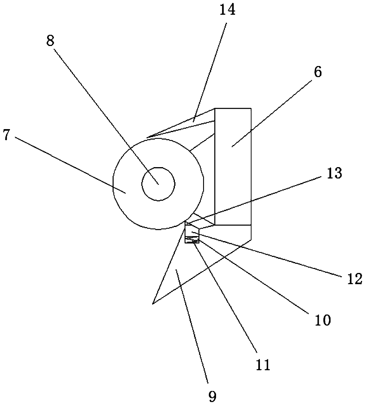
[0022] Embodiment 1: as Figure 1-2 As shown, a feeding bin for controlling blanking is characterized in that: rails 19 are fixedly installed on both sides of the inner wall of the feeding bin 1, and a moving seat 6 is movably connected to the two groups of rails 19, and the moving seat can Move horizontally on the track.
[0023] The right side of the inner cavity of the feeding bin 1 is fixedly equipped with a first motor 2, the left end of the first motor 2 is fixedly connected with a rotating rod 3, and the left end of the rotating rod 3 is provided with a first thread 4, and the rotating rod 3 is provided with a first thread 4. The right end of the rod 3 is provided with a second thread 5, and the first thread 4 and the second thread 5 are respectively connected with the two groups of the moving seats 6 through threads;
[0024] The direction of the first thread is opposite to that of the second thread, and the rotation of the rotating rod driven by the first motor can s...
Embodiment 2
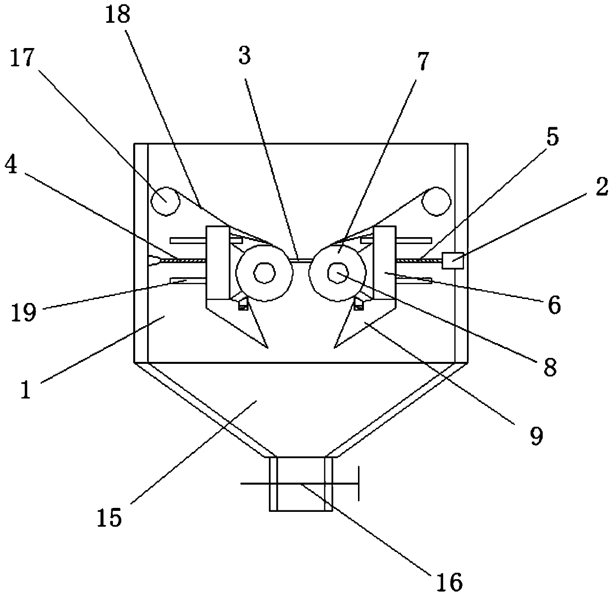
[0033] Embodiment 2: as Figure 1-3 As shown, a feeding bin for controlling blanking is characterized in that: rails 19 are fixedly installed on both sides of the inner wall of the feeding bin 1, and a moving seat 6 is movably connected to the two groups of rails 19, and the moving seat can Move horizontally on the track.
[0034] The right side of the inner cavity of the feeding bin 1 is fixedly equipped with a first motor 2, the left end of the first motor 2 is fixedly connected with a rotating rod 3, and the left end of the rotating rod 3 is provided with a first thread 4, and the rotating rod 3 is provided with a first thread 4. The right end of the rod 3 is provided with a second thread 5, and the first thread 4 and the second thread 5 are respectively connected with the two groups of the moving seats 6 through threads;
[0035] The direction of the first thread is opposite to that of the second thread, and the rotation of the rotating rod driven by the first motor can s...
PUM
 Abstract
Description
Claims
Application Information