
Automatic belt embossing machine

An embossing machine and belt technology, applied in the field of automatic belt embossing machines, can solve problems such as inflexible structure setting, troublesome product insertion and removal, and inability to push out the lower heating plate, so as to achieve rigorous and reasonable overall structure setting and structural setting Stable and tidy, the overall structure setting is reasonable

Pending Publication Date: 2020-02-25
蔡必建
View PDF0 Cites 0 Cited by
  • Summary
  • Abstract
  • Description
  • Claims
  • Application Information

AI Technical Summary

Problems solved by technology

[0004] The technical problem solved by the present invention is to overcome that although the belt embossing machine of the prior art has a large model, the structural setting is not flexible enough, the size of the mold between the heating plates cannot be adjusted, the size of the belt embossing is limited, and the putting in and taking out of the product is difficult at the same time. It is more troublesome, the lower heating plate cannot be pushed out, and the belt is not convenient enough to place, etc., which brings some inconvenience to the staff. An automatic belt embossing machine is provided.

Method used


Image

  • Automatic belt embossing machine
  • Automatic belt embossing machine
  • Automatic belt embossing machine

Examples


Embodiment Construction

[0025] The following will clearly and completely describe the technical solutions in the embodiments of the present invention with reference to the accompanying drawings in the embodiments of the present invention. Obviously, the described embodiments are only some, not all, embodiments of the present invention. Based on the embodiments of the present invention, all other embodiments obtained by persons of ordinary skill in the art without making creative efforts belong to the protection scope of the present invention.

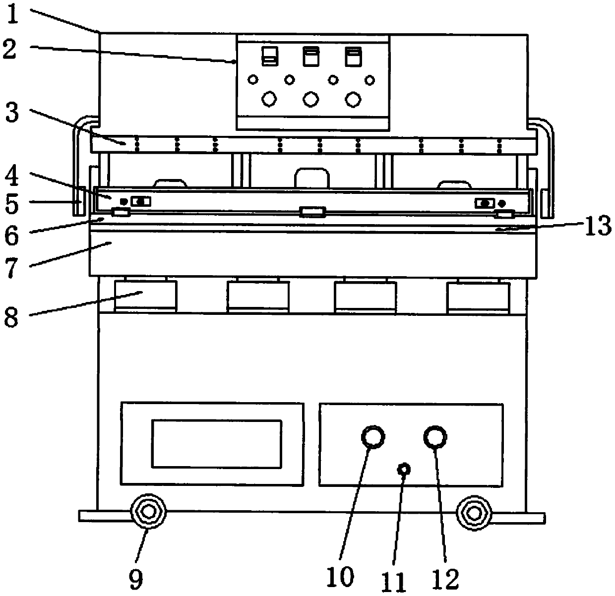
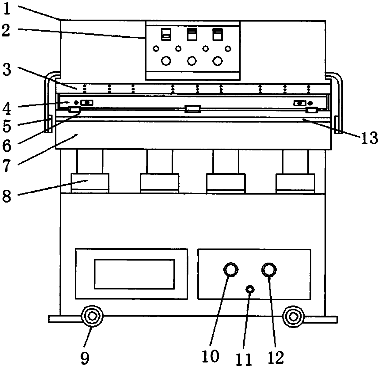
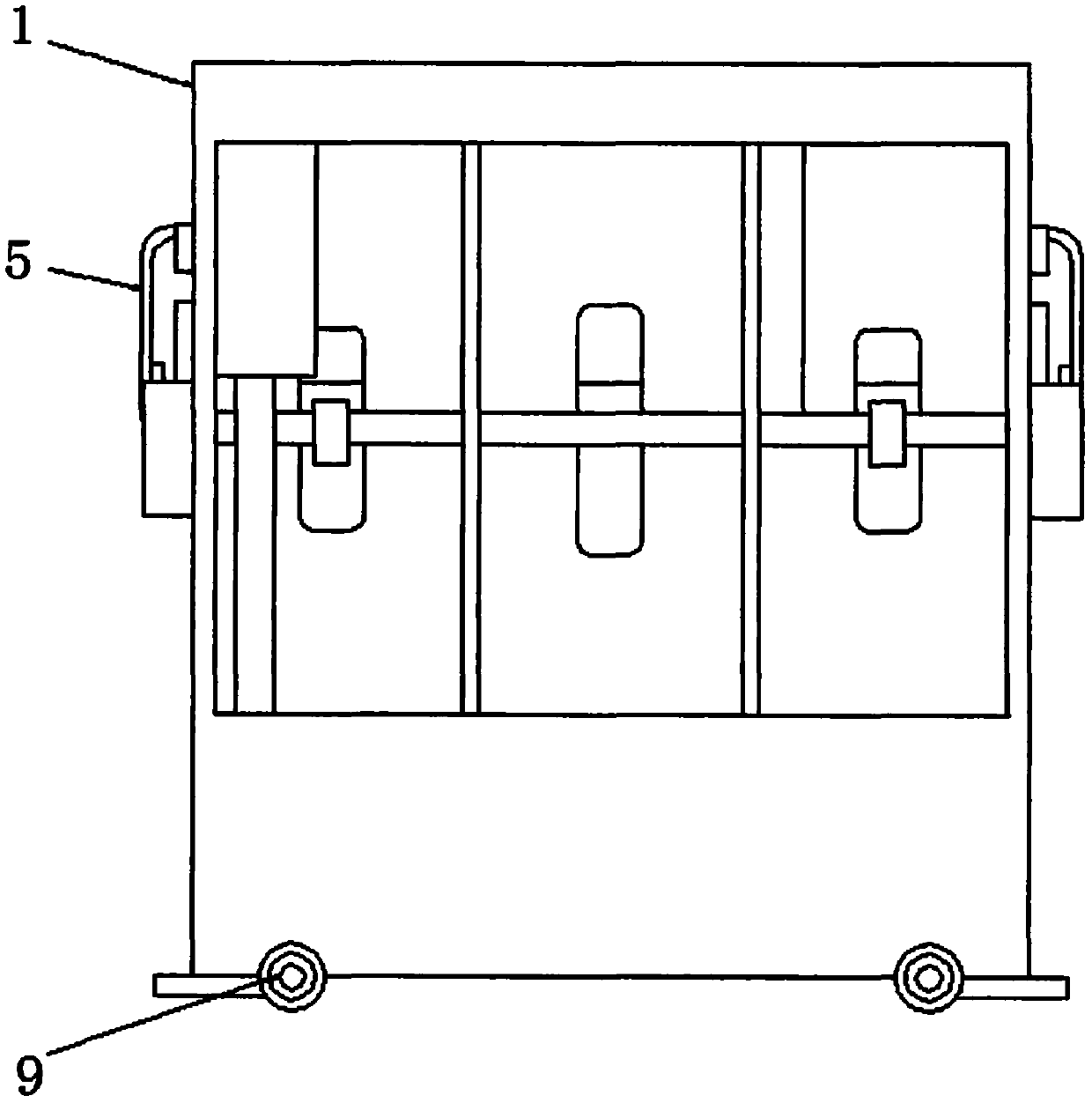
[0026] see Figure 1-7, the present invention provides a technical solution: an automatic belt embossing machine, including a frame 1, a control panel 2, an upper heating plate 3, a lower heating plate structure 4, a photoelectric switch reflector 5, a carriage 6, and a workbench 7 , the first telescopic oil cylinder 8, the roller 9, the total pressure gauge 10, the holding pressure gauge 11, the pressure relay 12, the storage table 13, the rear adjustment pla...


PUM


Abstract

The invention discloses an automatic belt embossing machine. The automatic belt embossing machine comprises a machine frame, an upper heating plate and a workbench, wherein a control panel is mountedon the upper part of the front surface of the machine frame, the upper heating plate is arranged below the control panel, a lower heating plate structure is arranged right below the upper heating plate, and the lower heating plate structure is slidably arranged on the upper surface of a carriage. According to the automatic belt embossing machine, the structural arrangement is reasonable, the automatic belt embossing machine is mainly divided into a machine frame structure, a control panel structure, an upper heating plate structure, the lower heating plate structure, an advancing and retreating structure and an up-down telescopic moving structure, the control panel controls the workbench to move up and down, so that the lower heating plate structure on the workbench is enabled to move up and down along with the carriage, then a second telescopic oil cylinder is controlled to be advanced to retreated, the whole lower heating plate structure is pushed out to enable an unprocessed belt tobe continuously placed, then the lower heating plate structure continues to be retracted to perform heating and embossing, mastering and controlling are facilitated, and the working efficiency can befavorably improved.

Description

technical field [0001] The invention relates to the technical field of belt processing equipment, in particular to an automatic belt embossing machine. Background technique [0002] In the field of belt manufacturing, after the leather has been cut and slitting, the surface of the belt needs to be embossed, and the embossing process is carried out by an embossing machine. The belt embossing machine mainly uses high-frequency, high-voltage rectification self-excited high-frequency electron tube oscillation Instantly generate electromagnetic wave current electric field, use processed PVC, TPU, EVA, PET and other leather materials in the electromagnetic wave electric field to generate polarized friction and heat generation in the leather's internal molecules, and add a certain pressure to make the required heat-sealing welding of the leather reach Welding and sealing effect, although the belt embossing machine of the prior art has a large model, the structural setting is not fl...

Claims


Application Information

Patent Timeline
Patent Type & Authority Applications(China)
IPC IPC(8): C14B1/56C14B17/14C14B17/10
CPCC14B1/56C14B17/14C14B17/10C14B2700/18
Inventor 蔡必建
Owner 蔡必建
Learn More