A method for acquiring time-domain waveforms of a spectrum scanning measurement device

A spectrum scanning and measurement device technology, which is applied in the direction of measurement devices, spectrum analysis, and measurement of electrical variables, can solve the problems of cost and volume increase, flexibility and practical limitations, etc., to achieve accurate measurement and improve the signal-to-noise ratio of the instrument Effect

Active Publication Date: 2021-06-04
UNIV OF ELECTRONICS SCI & TECH OF CHINA
View PDF5 Cites 0 Cited by
  • Summary
  • Abstract
  • Description
  • Claims
  • Application Information

AI Technical Summary

Problems solved by technology

However, the cost and volume of this method increase by tens of times, which makes it quite limited in flexibility and practicality.

Method used


Image

  • A method for acquiring time-domain waveforms of a spectrum scanning measurement device
  • A method for acquiring time-domain waveforms of a spectrum scanning measurement device
  • A method for acquiring time-domain waveforms of a spectrum scanning measurement device

Examples


Embodiment

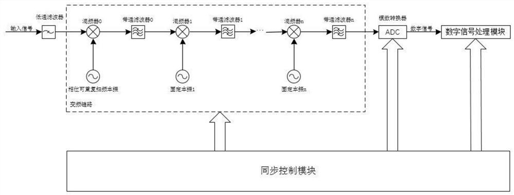
[0080] figure 2 It is a functional block diagram of a spectrum scanning measurement device.

[0081] In this example, if figure 2 As shown, a kind of spectrum scanning measuring device of the present invention comprises: low-pass filter, synchronous control module, frequency conversion link and analog-to-digital converter and digital signal processing module;

[0082] The low-pass filter is used to filter out the input high-frequency interference signal, preventing the high-frequency interference signal from entering the device in the form of a mirror image, and interfering with the measurement of the effective input signal;

[0083] The synchronization control module is used to control the frequency conversion link, the analog-to-digital converter and the digital signal processing module to perform synchronous coordination work according to the trigger of the same clock;

[0084] The frequency conversion link includes n+1 mixers, n+1 bandpass filters, n fixed local oscill...

example

[0141] In this example, combined with figure 2 , a specific hardware architecture of a two-stage frequency conversion is given, including:

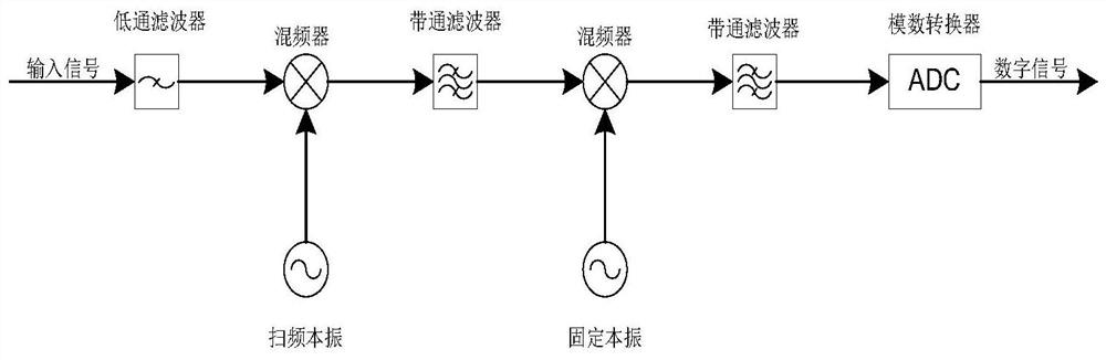
[0142] Image rejection is achieved using a low-pass filter (cutoff frequency 1.5GHz) and an IF scheme, followed by downconversion of the signal to an IF (30MHz) using a second-stage mixer.

[0143] The first-stage local oscillator is a phase-repeatable frequency-sweeping local oscillator, and for the signal of this embodiment, it sweeps from 2 GHz to 3.5 GHz.

[0144] The second level of local oscillator is a point frequency signal (1970MHz), which mainly realizes the down-conversion function.

[0145] The sampling rate of the ADC is 200MHz, which is used to complete the analog-to-digital conversion of the intermediate frequency signal.

[0146] Band-pass filter (1975MHz-2025MHz) and band-pass filter (20MHz-40MHz) are mainly used for filtering spurious and image signals after mixing.

[0147] In spectrum measurement, the first phase c...


PUM


Abstract

The invention discloses a frequency spectrum scanning measurement device and a time domain waveform acquisition method, which uses a phase-repeatable signal source as a frequency-sweeping local oscillator, and controls the local oscillator to perform a rough frequency scan with a known scanning time interval through software; Perform fast Fourier transform on the intermediate frequency signal to realize spectrum subdivision; then restore and calibrate the amplitude and phase of the signal measurement value respectively. The amplitude recovery can be calibrated directly by using the standard signal and calibrated by the calibration value; The recovery of the phase needs to first restore the phase offset caused by the non-real-time measurement of the frequency sweep structure, and then eliminate the phase influence of the LO, and finally use the comb wave transmitter and multiple sine waves to calibrate the phase of the entire system; it is completed in the frequency domain After the recovery of the signal amplitude and phase, the time-domain waveform of the measured signal can be obtained by vector superposition of all spectral components.

Description

technical field [0001] The invention belongs to the technical field of electronic measuring instruments, and more specifically relates to a spectrum scanning measuring device and a method for acquiring time-domain waveforms. Background technique [0002] It can be known from the Fourier transform that the signal can be expressed in both the time domain form and the frequency domain form. Both frequency domain and time domain are very important for analyzing signals. For electrical signals, oscilloscopes and spectrum analyzers are two typical instruments for analyzing signal time domain and frequency domain respectively. The oscilloscope uses a high-speed analog-to-digital conversion circuit (ADC) to directly convert the analog signal into a digital signal, and then display it. It is a direct time-domain measurement instrument. The spectrum analyzer uses a superheterodyne structure, uses a mixer to mix the measured signal and the scanned local oscillator signal to a fixed i...

Claims


Application Information

Patent Timeline
Patent Type & Authority Patents(China)
IPC IPC(8): G01R23/173G01R23/167
CPCG01R23/167G01R23/173
Inventor 高博童玲宫珣王培丞董雪建
Owner UNIV OF ELECTRONICS SCI & TECH OF CHINA
Why Eureka
Try Eureka