
Micro-grid architecture light storage complementary self-powered bin type energy storage system based on different voltage levels

A technology of energy storage system and power supply system, which is applied in the field of warehouse energy storage system, and can solve the problems of increased safe operation of batteries, large self-consumption, hidden dangers, etc.

Pending Publication Date: 2020-02-25
周锡卫
View PDF0 Cites 0 Cited by
  • Summary
  • Abstract
  • Description
  • Claims
  • Application Information

AI Technical Summary

Problems solved by technology

At the same time, many problems have also arisen, such as: the self-consumption is relatively large, and the self-consumption is generally about 10% or more of the power supply capacity of the energy storage system; especially the warehouse energy storage system is usually placed in the open air, and the sun Exposure to the sun causes the top insulation layer of the container where the battery is installed to be sun-drenched, and the temperature inside the container rises. This requires a larger-scale temperature control system and more power consumption, which also increases hidden dangers to the safe operation of the battery.

Method used


Image

  • Micro-grid architecture light storage complementary self-powered bin type energy storage system based on different voltage levels
  • Micro-grid architecture light storage complementary self-powered bin type energy storage system based on different voltage levels
  • Micro-grid architecture light storage complementary self-powered bin type energy storage system based on different voltage levels

Examples


Embodiment Construction

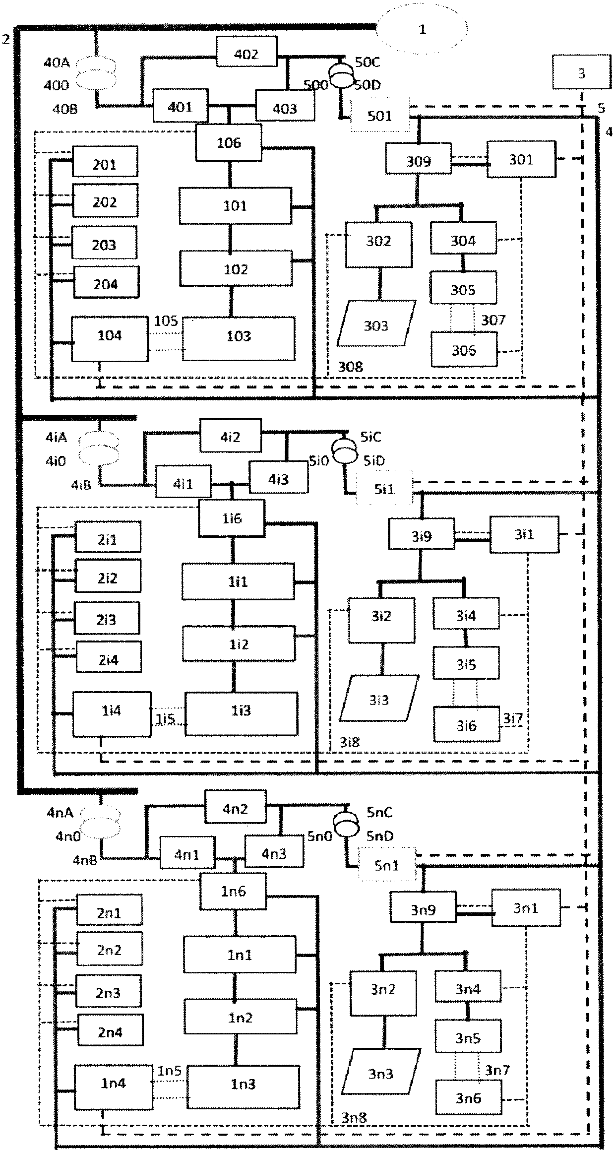
[0030] As an implementation example, a warehouse-type energy storage system based on a microgrid architecture with different voltage levels and self-storage complementary self-power supply will be described with reference to the accompanying drawings. However, the technology and solution of the present invention are not limited to the content given in this implementation example.

[0031] Such as figure 1As shown, a warehouse-type energy storage system based on a microgrid architecture with different voltage levels and self-supply power storage complementary to solar energy storage mainly includes: power grid (1), grid-level power lines (2), and microgrid management and control system EMS ( 3), micro-grid level power line (4), micro-grid communication bus for solar-storage complementary power supply (5), the first solar-storage complementary power supply control module (301), the first solar-storage power supply photovoltaic inverter (302), the first Photovoltaic power genera...

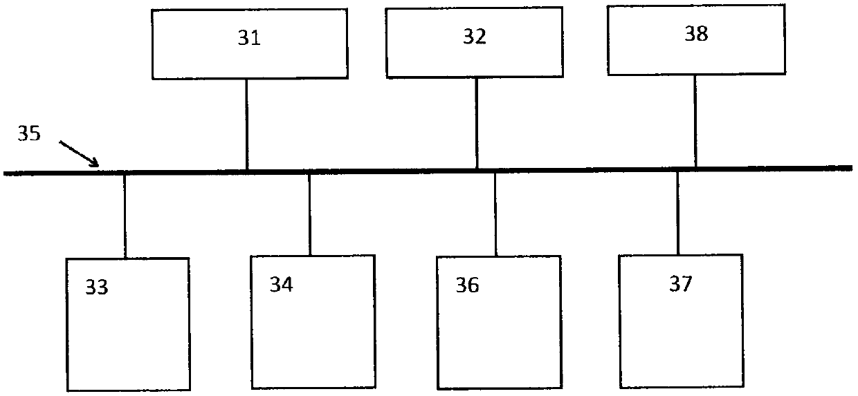
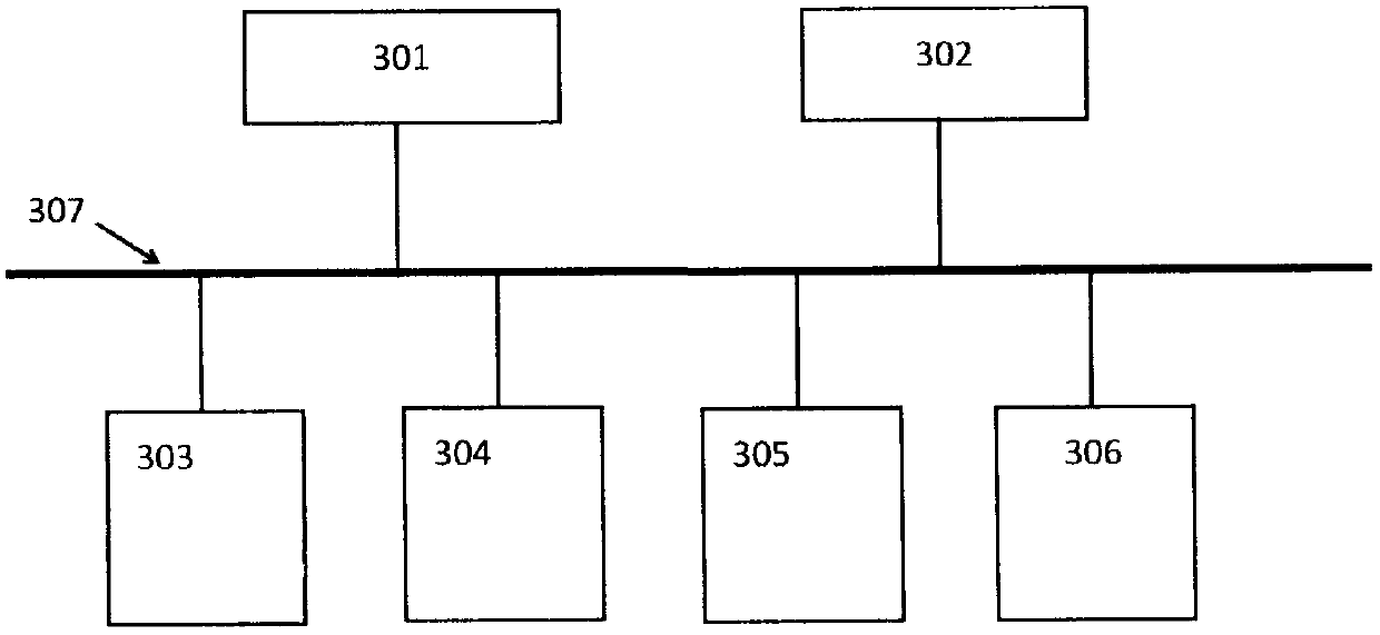

PUM


Abstract

The invention belongs to the technical field of electrochemical energy storage application and particularly relates to a micro-grid architecture light storage complementary self-powered bin type energy storage system based on different voltage levels. Three voltage levels of high-voltage grid connection of an energy storage system, a low-voltage alternating-current port of an energy storage inverter and a station service power supply path of conventional voltage are utilized, and a factory power supply system with three kinds of power supply frameworks including an optical storage complementary micro-grid auxiliary power supply system with a conventional voltage grade, a large energy storage optical storage micro-grid for energy storage and power supply of an energy storage inverter composed of a transformer and an electric control switch circuit, and a grid-connected optical storage micro-grid connected with the power grid are constructed. The safety and the economy of the factory power supply are greatly improved. The system is further characterized in that a photovoltaic panel array is installed on a container of the bin type energy storage system to shade the energy storage container and generate power to supplypower to the auxiliary power supply of the bin type energy storage system; photovoltaic residual power is supplied to the bin type energy storage system and to the privately used residual power for surfing the Internet; investment and power consumption are reduced; and efficiency and commercial income are improved.

Description

technical field [0001] The invention belongs to the technical field of electrochemical energy storage applications, and in particular relates to a warehouse-type energy storage system based on micro-grid architectures with different voltage levels and self-storage complementary self-power supply. Background technique [0002] The energy storage system focuses on reducing abandoned wind and light and improving the utilization rate of new energy, relying on peak regulation and frequency regulation to improve the economy and safety of power grid operation, complementing energy storage and new energy, and closely interacting between energy storage and power grid peak regulation and frequency regulation The commercial application of energy storage systems with the goal of interconnection and interoperability of electric energy has been favored and supported by the government and the industry. Energy storage systems are widely used in peak regulation and frequency modulation, peak ...

Claims


Application Information

Patent Timeline
IPC IPC(8): H02J3/38H02J3/32
CPCH02J3/32Y02E10/56Y02E70/30Y02P80/20
Inventor 周锡卫
Owner 周锡卫
Learn More