Super magnetostrictive actuator

A technology of giant magnetostriction and giant magnetostrictive rod, applied in piezoelectric effect/electrostrictive or magnetostrictive motors, generators/motors, electrical components, etc., can solve the problem that the driver technology cannot be well satisfied Accuracy requirements, restrictions on the application of magnetostrictive drives, small output displacement of magnetostrictive materials, etc., to achieve the effects of high test efficiency and test accuracy, short test time, and large output force

Inactive Publication Date: 2020-02-25
HUNAN UNIV OF SCI & ENG
View PDF5 Cites 3 Cited by
  • Summary
  • Abstract
  • Description
  • Claims
  • Application Information

AI Technical Summary

Problems solved by technology

However, when the giant magnetostrictive driver is working, the thermal deformation of the giant magnetostrictive rod caused by the heating of the coil and the maximum output of the controllable displacement of the giant magnetostrictive driver are both tens of microns, which are in the same order of magnitude. Greater impact
At the same time, the heat dissipated by the coil will not only be transferred to the magnetostrictive rod, but will also be transferred from the two ends and the outer surface of the coil to the base, end cover and shell respectively, resulting in its deformation, which will also affect the output of the driver. precision
Therefore, in long-time, high-current, and ultra-high-precision workplaces, the existing driver technology cannot well meet the accuracy requirements
As a new type of driver technology, the magnetostrictive drive has the advantages of high frequency, high Curie temperature, high controllability, fast response, fast switching speed, low power consumption, and small environmental factors. However, due to the output displacement of the magnetostrictive material Shortcomings such as small size restrict the application of magnetostrictive drives

Method used


Image

  • Super magnetostrictive actuator
  • Super magnetostrictive actuator
  • Super magnetostrictive actuator

Examples


Embodiment 1

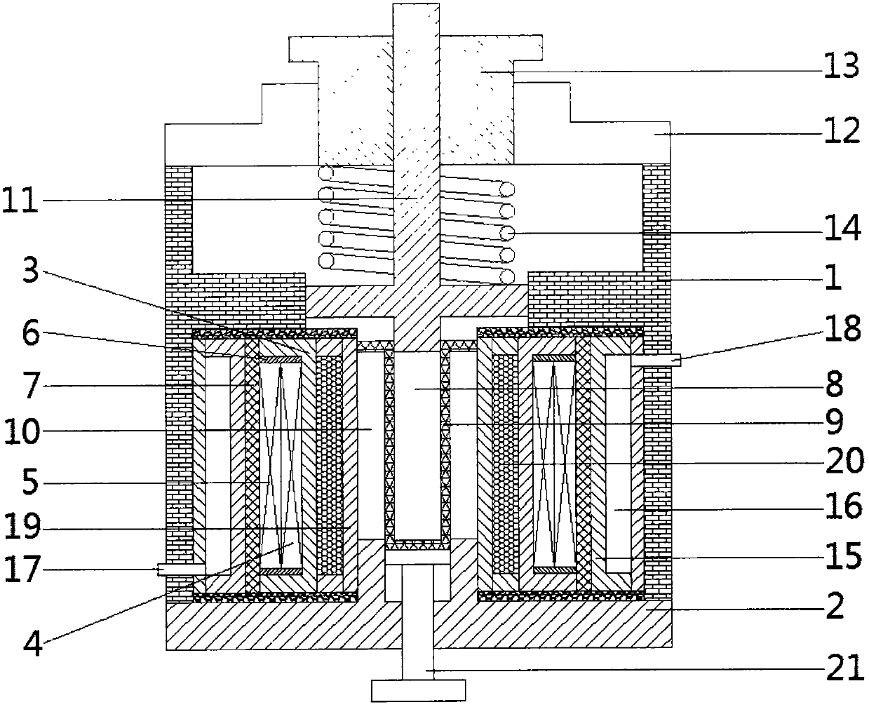
[0025] see figure 1 , a giant magnetostrictive driver, comprising a housing 1 and a base 2 arranged at the bottom of the housing 1, the housing 1 is provided with a magnetic field generating device, a cooling device, a pretensioning device and a positioning device;

[0026] The magnetic field generating device includes a coil bobbin 3 arranged on the lower side of the housing 1 and a permanent magnet 7 arranged outside the coil bobbin 3 , a drive coil 4 is wound outside the coil bobbin 3 , and a drive coil 4 is wound outside the drive coil 4 . A bias coil 5 is connected, and a heat shield 6 is provided at the contact between the inside of the bobbin 3 and the driving coil 4 and the bias coil 5. A cavity is provided in the middle of the bobbin 3 and a U is installed inside the cavity. shaped tube 9, a first giant magnetostrictive rod 8 is placed inside the open end of the U-shaped tube 9, and two second giant magnetostrictive rods 8 are placed symmetrically on the outside of th...

Embodiment 2

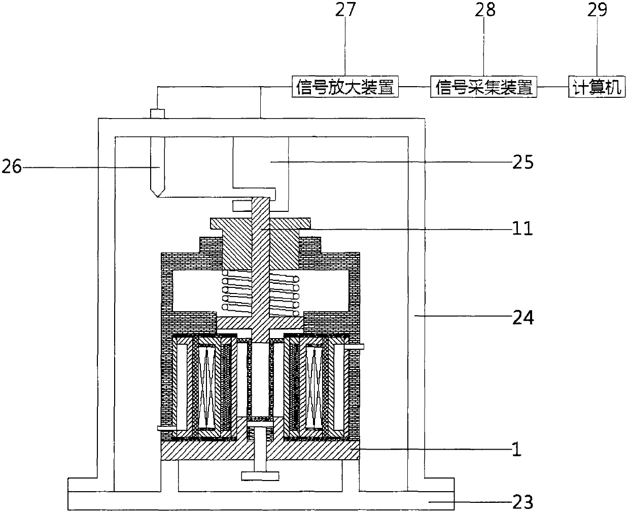
[0037] see Figure 1-4 , a giant magnetostrictive driver, comprising a housing 1 and a base 2 arranged at the bottom of the housing 1, the housing 1 is provided with a magnetic field generating device, a cooling device, a pretensioning device and a positioning device;

[0038] The magnetic field generating device includes a coil bobbin 3 arranged on the lower side of the housing 1 and a permanent magnet 7 arranged outside the coil bobbin 3 , a drive coil 4 is wound outside the coil bobbin 3 , and a drive coil 4 is wound outside the drive coil 4 . A bias coil 5 is connected, and a heat shield 6 is provided at the contact between the inside of the bobbin 3 and the driving coil 4 and the bias coil 5. A cavity is provided in the middle of the bobbin 3 and a U is installed inside the cavity. shaped tube 9, a first giant magnetostrictive rod 8 is placed inside the open end of the U-shaped tube 9, and two second giant magnetostrictive rods 8 are placed symmetrically on the outside of...


PUM


Abstract

The invention discloses a super magnetostrictive actuator. The actuator comprises a shell and a base arranged at the bottom of the shell; a magnetic field generating device, a cooling device, a pre-tightening device and a positioning device are arranged in the shell 1; and the actuator also comprises a detection device used for carrying out performance detection on the super magnetostrictive actuator. According to the invention, a water cooling mechanism and a phase-change material are combined for carrying out temperature control, the water cooling mechanism is used for cooling the outer sideof a coil, and the phase-change material is used for cooling the inner side of the coil, so that the output precision of the giant magnetostrictive actuator is improved, and long-time stable work isguaranteed; the size is small, the weight is light, the output displacement is large, and the output force is large; the pre-pressure and the bias magnetic field are adjustable; the output displacement is big and output force linearity is good; the response speed is high, the control precision is high, and the eddy current groove can further improve the control precision of the output displacement; and meanwhile, a test system composed of a sensor, a signal amplification device and a computer is used for detecting the driving performance of a driver, so the test time is short, and the test efficiency and the test precision are high.

Description

technical field [0001] The invention relates to the technical field of giant magnetostriction, in particular to a giant magnetostriction driver. Background technique [0002] Due to the change of the magnetization state at room temperature, its length and volume will change greatly, that is, the magnetostrictive material with a large magnetostrictive coefficient is called giant magnetostrictive material (GMM), because most of them are rare earth Construction, also known as rare earth giant magnetostrictive materials. This material has high heat-resistant temperature and strong magnetostriction. At room temperature, the conversion rate between mechanical energy and electrical energy is high, the energy density is high, the response speed is fast, the reliability is good, and the driving method is simple. However, when the giant magnetostrictive driver is working, the thermal deformation of the giant magnetostrictive rod caused by the heating of the coil and the maximum outp...

Claims


Application Information

Patent Timeline
Patent Type & Authority Applications(China)
IPC IPC(8): H02N2/04
CPCH02N2/04H02N2/009H02N2/0075H02N2/005
Inventor 张贤才
Owner HUNAN UNIV OF SCI & ENG
Why Eureka
Try Eureka