Ceramic chopper

A rivet and ceramic technology, applied in the field of ceramic rivets, can solve the problem that the tip is not directional, and achieve the effects of reducing the degree of gold retention at the tip, improving stability and prolonging service life.

Pending Publication Date: 2020-02-28
苏州三环科技有限公司 +1
View PDF9 Cites 2 Cited by
  • Summary
  • Abstract
  • Description
  • Claims
  • Application Information

AI Technical Summary

Problems solved by technology

[0009] The object of the present invention is to overcome the deficiencies of the prior art and provide a ceramic rivet, whic

Method used


Image

  • Ceramic chopper
  • Ceramic chopper
  • Ceramic chopper

Examples


Embodiment 1

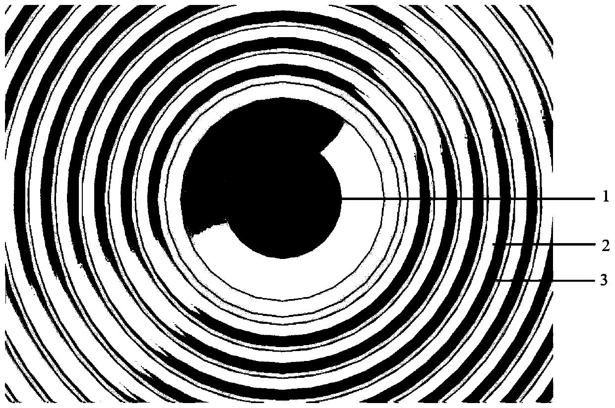
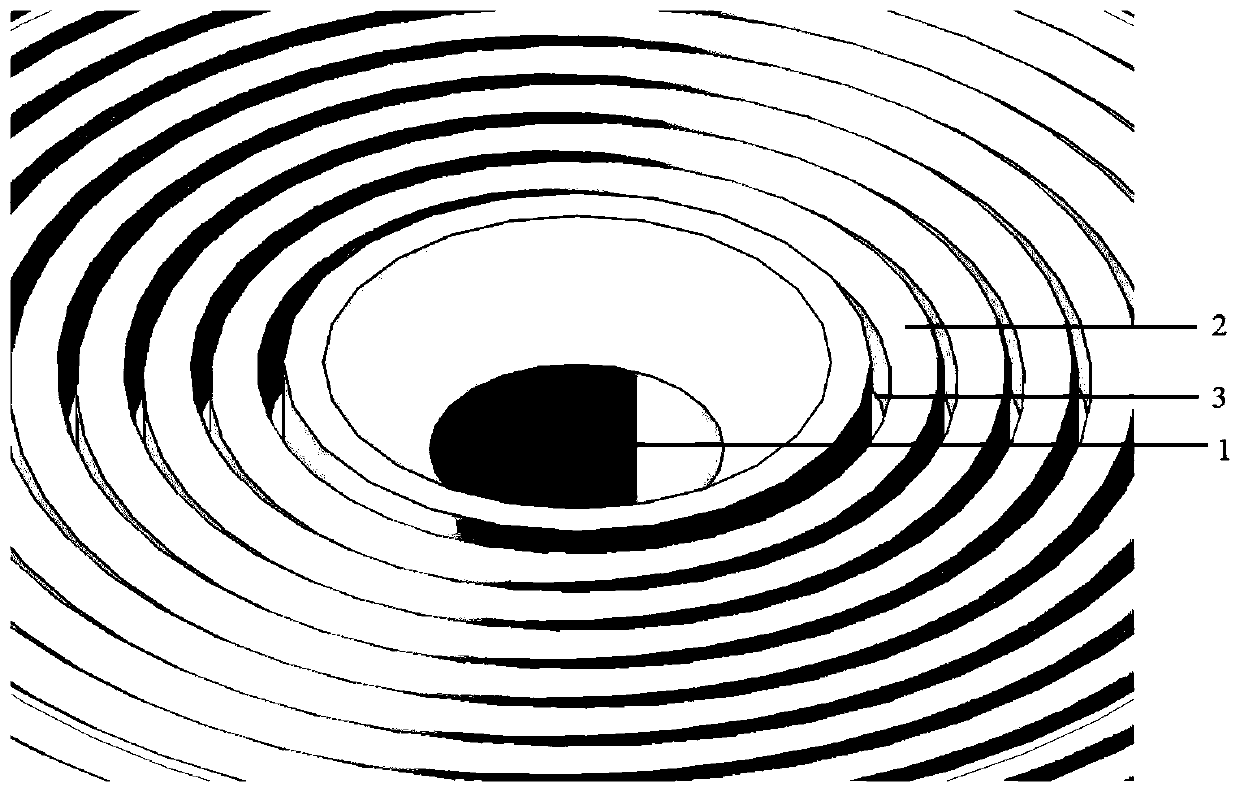
[0042] As an embodiment of the ceramic rivet of the present invention, the ceramic rivet of this embodiment includes a body, a welding tip located at one end of the body and a hole, the hole extends along the longitudinal axis of the body and the welding tip, and the tip of the welding tip surface as Figure 1-2As shown, there is a multi-level concentric ring with the geometric center of the welding tip as the center. The multi-level concentric ring is arranged in concave and convex alternately, and the highest point of the convex concentric ring in the multi-level concentric ring and the concave concentric circle The lowest point of the ring forms a height difference, and the height difference is 6 μm; each convex concentric ring is composed of independently arranged ring protrusions, and the height of each ring protrusion is the same; each convex concentric ring The widths are all the same, and the width of the convex concentric rings is 3 μm; the width of each concave conce...

Embodiment 2

[0047] The ceramic rivet of the present embodiment is basically the same as that of Embodiment 1, the difference is that the highest point of the convex concentric ring and the lowest point of the concave concentric ring in the multi-stage concentric ring of the ceramic rivet of the present embodiment form a height difference, The height difference is 10 μm.

Embodiment 3

[0049] The ceramic rivet of the present embodiment is basically the same as that of Embodiment 1, the difference is that the highest point of the convex concentric ring and the lowest point of the concave concentric ring in the multi-stage concentric ring of the ceramic rivet of the present embodiment form a height difference, The height difference is 15 μm.


PUM

PropertyMeasurementUnit
Widthaaaaaaaaaa
Widthaaaaaaaaaa
Surface roughnessaaaaaaaaaa

Abstract

The invention discloses a ceramic chopper. The chopper comprises a body, a welding nozzle at one end of the body, and a hole. The hole extends along the longitudinal axis of the body and the welding nozzle. The surface of the tip end of the welding nozzle is provided with multi-stage concentric annuluses with the geometric center of the welding nozzle as the circle center. The multi-stage concentric annuluses are arrayed in a concave-convex staggered mode. The highest point of the convex concentric annuluses and the lowest point of the concave concentric annuluses in the multi-stage concentricannuluses form the height difference which is 6-15 [mu]m. The multi-stage concentric annuluses which are arrayed in the concave-convex staggered mode are designed on the surface of the tip end, so the roughness of the surface of the tip end can be increased, the wearable area of the convex parts is increased, no directional problem exists in use, and the consistency and stability of welding spotscan be improved. The convex parts are connected into the annuluses to form a stable structure, and the stability and wear resistance of the tip end are improved. The highest point of the convex concentric annuluses and the lowest point of the concave concentric annuluses form the high height difference, wear is resisted, and the service life is easily prolonged.

Description

technical field [0001] The invention relates to the technical field of riving knives, in particular to a ceramic riving knife. Background technique [0002] Wire bonding is the mainstream method of internal connection in packages. It uses heat, pressure and ultrasonic energy to tightly weld the bonding wires to the metal pads to realize signal transmission between chips and between chips and packages. The riving knife is an important tool in the wire bonding process, and its performance determines the reliability of the bonding, but the tip of the traditional riving knife generally has a polished surface, which is easy to wear, has a short life, and has insufficient surface roughness. [0003] JPS62190343U discloses a rivet for improving wire bonding strength. Holes are distributed in the welding tip of the welding rivet, and the tip surface of the welding tip is composed of alternately distributed convex parts and concave parts, and the highest point of the convex part reac...

Claims


Application Information

Patent Timeline
IPC IPC(8): B23K20/10B23K20/26
CPCB23K20/10B23K20/26
Inventor 邱基华黄雪云郑镇宏
Owner 苏州三环科技有限公司
Why Eureka
Try Eureka