
Electric tower steel component welding device

A technology for welding devices and steel components, applied in auxiliary devices, welding equipment, auxiliary welding equipment, etc., can solve the problems of unfavorable outdoor working environment, inconvenient carrying of protective gear, complex use conditions and long-distance distribution, and achieve convenient outdoor work Effect

Pending Publication Date: 2020-02-28
东台市新杰科机械有限公司
View PDF7 Cites 1 Cited by
  • Summary
  • Abstract
  • Description
  • Claims
  • Application Information

AI Technical Summary

Problems solved by technology

[0002] The connection methods in the transmission angle steel tower structure mainly include riveting and welding. With the continuous development and upgrading of the power grid, the transmission tower is also developing in the direction of large-scale, steel structure and scale, and the required component bearing capacity is also getting higher and higher. For The structural design and steel use of transmission towers put forward higher requirements. At the same time, transmission towers have the characteristics of long-term outdoor operation, complex use conditions, and long-distance distribution.
[0003] The common welding equipment currently on the market are all models suitable for large steel plants. They are bulky and difficult to move, and cannot adapt to the conditions of long-term outdoor operation for the welding of electric tower steel components. In addition, goggles, protective clothing, etc. are often required to be used during use. Protective gear to prevent workers from being injured during welding, but these protective gears are extremely inconvenient to carry and are not conducive to long-term outdoor working environments

Method used


Image

  • Electric tower steel component welding device
  • Electric tower steel component welding device
  • Electric tower steel component welding device

Examples


Embodiment Construction

[0026] The following will clearly and completely describe the technical solutions in the embodiments of the present invention with reference to the accompanying drawings in the embodiments of the present invention. Obviously, the described embodiments are only some, not all, embodiments of the present invention. Based on the embodiments of the present invention, all other embodiments obtained by persons of ordinary skill in the art without making creative efforts belong to the protection scope of the present invention.

[0027] In the description of the present invention, it should be noted that the terms "center", "upper", "lower", "left", "right", "vertical", "horizontal", "inner", "outer" etc. The indicated orientation or positional relationship is based on the orientation or positional relationship shown in the drawings, and is only for the convenience of describing the present invention and simplifying the description, rather than indicating or implying that the referred d...


PUM


Abstract

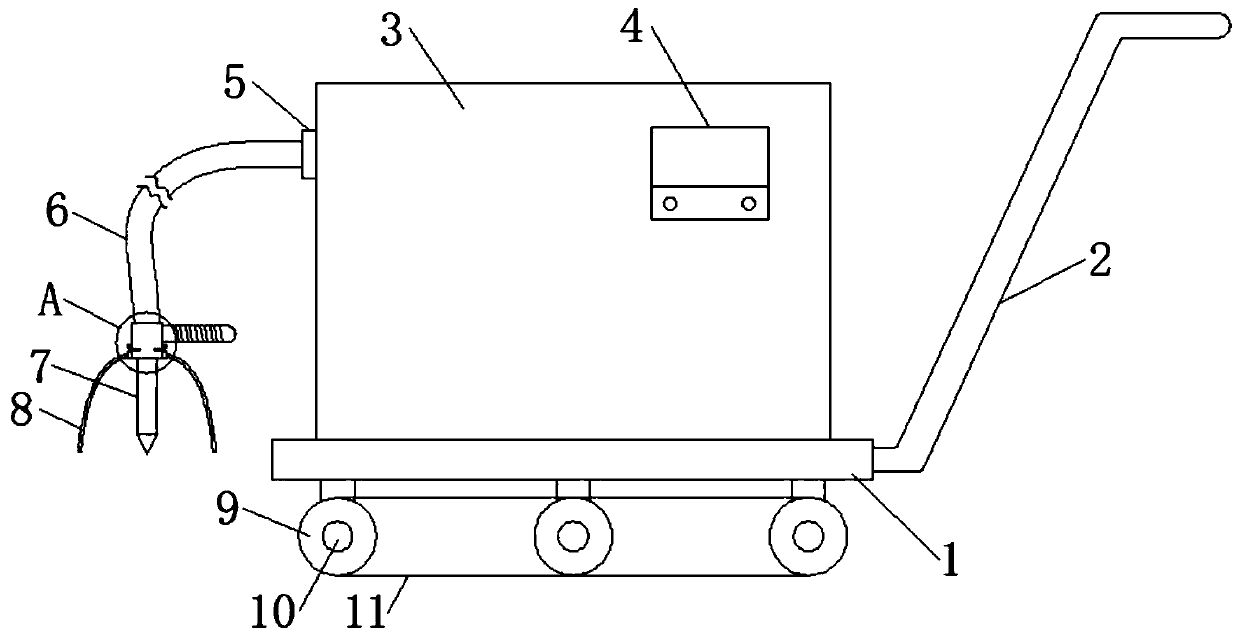
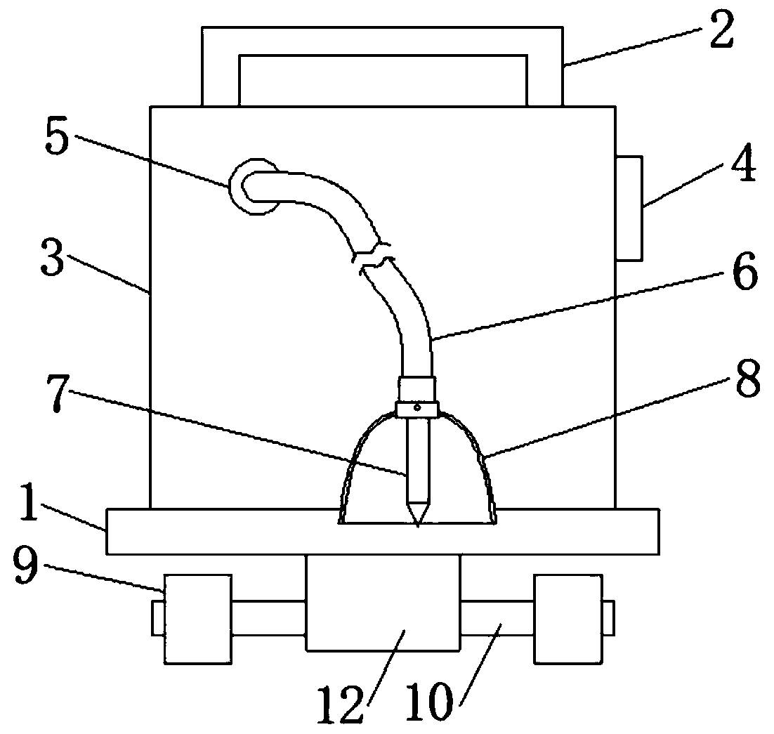
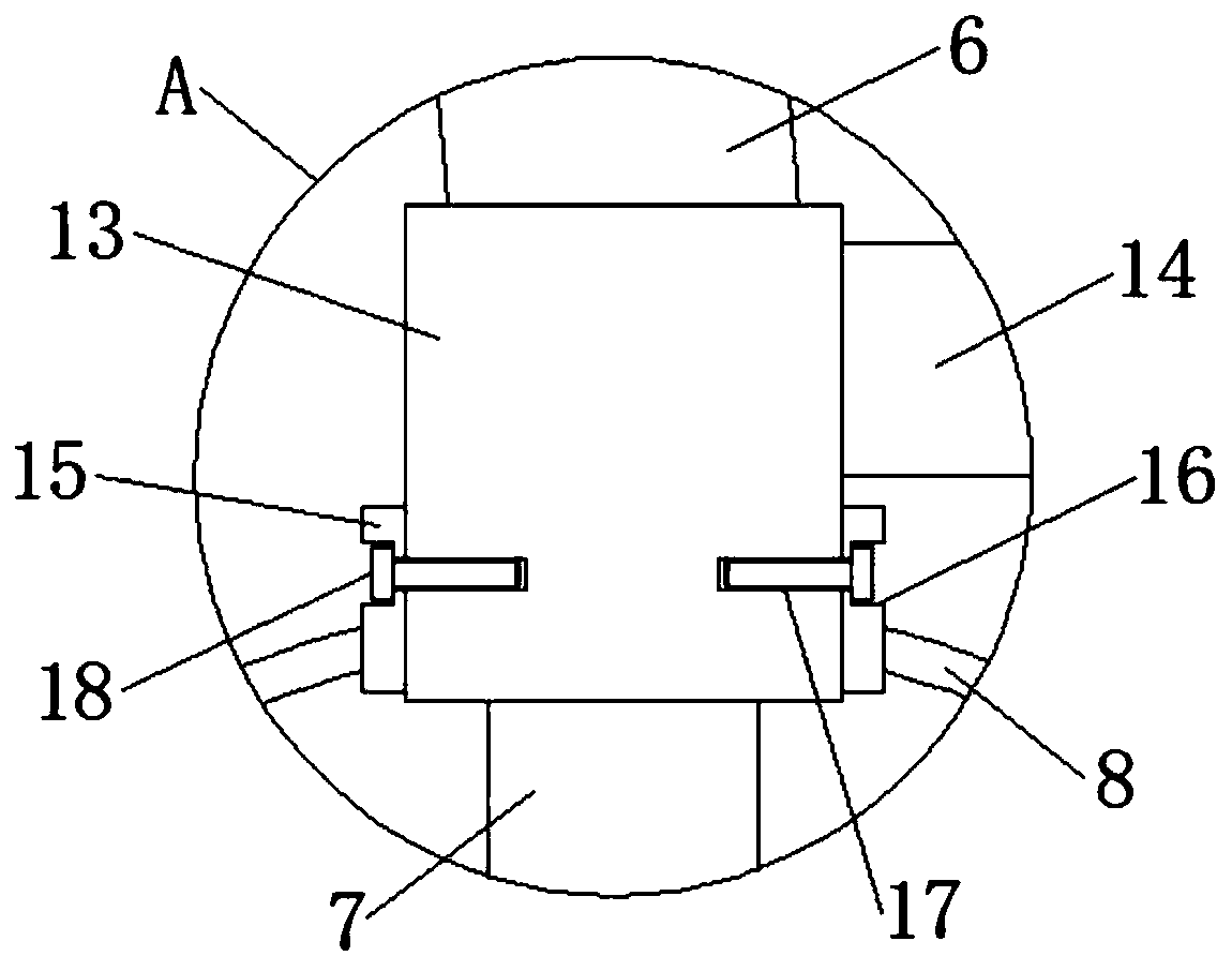
The invention discloses an electric tower steel component welding device which comprises a base; the two ends of a rotary shaft penetrate through the centers of idler wheels and are fixedly connectedwith the idler wheels; caterpillar band is externally connected with the external diameter parts of the three idler wheels on the same side of the bottom of the base; an electric welding machine caseis fixedly connected with the top of the base; an electric welding head is fixedly connected with the bottom of a connecting piece; a fixed piece is connected with the external diameter part of the lower part of the connecting piece through a sleeve; and the outer side wall of the lower part of the fixed piece is fixedly connected with the top end of a protective cover. According to the electric tower steel component welding device, the caterpillar band is additionally mounted at the external parts of the idler wheels, so that the welding device can be adapted to various terrains during the moving process and is particularly suitable for long-time outdoor movement; in addition, the protective cover adopts the transparent electric welding goggle lens glass texture and does not affect checking the welded part during the welding operation process; and the semi-circular appearance can prevent an operator from being injured, so that various protective tools do not need to be carried, outdoor operation is more convenient, and the electric tower steel component welding device deserves vigorous popularization.

Description

technical field [0001] The invention relates to the technical field of steel processing equipment, in particular to a welding device for electric tower steel components. Background technique [0002] The connection methods in the transmission angle steel tower structure mainly include riveting and welding. With the continuous development and upgrading of the power grid, the transmission tower is also developing in the direction of large-scale, steel structure and scale, and the required component bearing capacity is also getting higher and higher. For The structural design and steel use of transmission towers put forward higher requirements. At the same time, transmission towers have the characteristics of long-term outdoor operation, complex use conditions, and long-distance distribution. [0003] The common welding equipment currently on the market are all models suitable for large steel plants. They are bulky and difficult to move, and cannot adapt to the conditions of lo...

Claims


Application Information

Patent Timeline
IPC IPC(8): B23K37/00F16P1/02
CPCB23K37/00B23K2103/04F16P1/02
Inventor 李俊东夏海荣顾合兵成新华
Owner 东台市新杰科机械有限公司
Learn More