Eureka AIR delivers breakthrough ideas for toughest innovation challenges, trusted by R&D personnel around the world.

Engine tail gas aftertreatment mixing device

A tail gas post-treatment and mixing device technology, which is applied in exhaust gas treatment, exhaust devices, engine components, etc., can solve the problems of low crystallization risk of gas flow rate distribution uniformity, poor gas flow rate distribution uniformity, urea crystallization, and high mixing uniformity. , to achieve the effect of preventing urea crystallization, improving conversion efficiency, and less internal components

Active Publication Date: 2020-02-28
无锡亿利环保科技有限公司
View PDF7 Cites 1 Cited by
  • Summary
  • Abstract
  • Description
  • Claims
  • Application Information

AI Technical Summary

Problems solved by technology

[0005] In view of the disadvantages of poor gas flow velocity distribution uniformity, easy formation of urea crystals, poor mixing uniformity, and large gas flow pressure drop in the existing tail gas post-treatment mixing device, the applicant provides a tail gas post-treatment mixing device with a reasonable structure. High homogeneity, low risk of crystallization, high mixing uniformity and low airflow pressure drop

Method used


Image

  • Engine tail gas aftertreatment mixing device
  • Engine tail gas aftertreatment mixing device
  • Engine tail gas aftertreatment mixing device

Examples


Embodiment 1

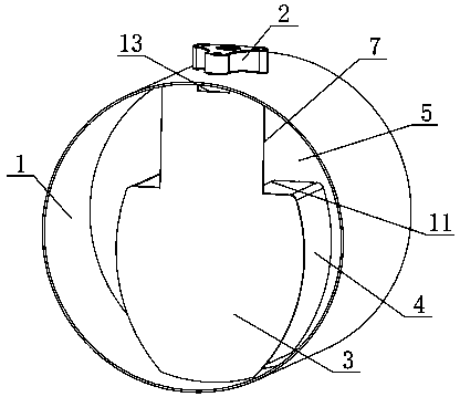
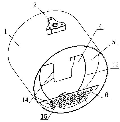
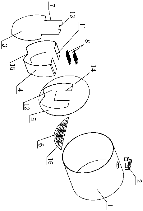
[0045] Such as figure 1 , figure 2 , image 3 As shown, the inner cavity of the cylindrical shell 1 of the present invention is provided with an inner shell 4, and the inner shell 4 is located at the middle and lower part of the inner cavity; as Figure 4 As shown, the inner shell 4 divides the inner cavity of the outer shell 1 into an air inlet cavity 9 outside the inner shell 4 and an air outlet cavity 10 inside the inner shell 4; the upper surface of the inner shell 4 is provided with a through air inlet 11 , the air inlet 11 communicates with the air inlet chamber 9 and the air outlet chamber 10 . Such as figure 1 , image 3 As shown, the front end face of the inner shell 4 is provided with a front baffle 3, as figure 2 , image 3 As shown, the rear end of the inner shell 4 is fixed with a tailgate 5, and the tailgate 5 is welded and fixed on the shell 1; the shell 1 is provided with a nozzle seat 2 above the air inlet 11, and the nozzle seat 2 and the urea nozzle ...

Embodiment 2

[0054] Such as Figure 5 , Figure 6As shown, an inner shell 4 is arranged in the inner cavity of the outer shell 1, and the inner shell 4 is located at the middle and lower part of the inner cavity; the inner shell 4 separates the inner cavity of the outer shell 1 into an air intake cavity 9, and an air outlet chamber 10 located inside the inner shell 4; The front end of the inner shell 4 is covered with a front baffle 3, the rear end of the inner shell 4 is fixed with a back baffle 5, and the back baffle 5 is welded and fixed on the outer shell 1; the front and rear sides of the air inlet 11 of the inner shell 4 The first shielding plate 17 and the second shielding plate 19 are fixedly arranged respectively, the upper ends of the first shielding plate 17 and the second shielding plate 19 are fixed on the casing 1, and the bottoms of the first shielding plate 17 and the second shielding plate 19 extend into In the air outlet chamber 10; the first shielding plate 17 is locat...


PUM


Abstract

The invention discloses an engine tail gas aftertreatment mixing device. An inner housing divides the interior of an outer housing into a gas inlet cavity and a gas outlet cavity, wherein a gas inletcommunicating with the gas inlet cavity and the gas outlet cavity is formed in the inner housing; a front baffle is arranged on one end face of the inner housing; a rear baffle is arranged at the other end of the inner housing; and a gas outlet is formed in the position, corresponding to the inner housing, of the rear baffle. According to the engine tail gas aftertreatment mixing device, the gas inlet cavity and the gas outlet cavity directly communicate through the gas inlet in the inner housing, no other blocking element exists between the gas inlet cavity and the gas outlet cavity, tail gasflow in the gas inlet cavity can smoothly enter the gas outlet cavity, the gas flow pressure drop is small, the tail gas flow entering the gas inlet cavity directly blows the wall face of the front baffle and the outer wall face of the inner housing and preheats all the wall faces, urea liquid drops falling on all the wall faces sufficiently absorb heat and volatilize, the urea crystallization risk is reduced, the volatilization rate of the urea liquid drops is increased, and then the NOX conversion efficiency is improved.

Description

technical field [0001] The invention relates to the technical field of engine exhaust aftertreatment, in particular to an engine exhaust aftertreatment mixing device. Background technique [0002] At present, in the engine exhaust after-treatment system, the selective catalytic reduction technology (SCR) is usually used to post-treat the exhaust of the engine, and the urea aqueous solution is sprayed into the exhaust after-treatment mixing device, and the urea aqueous solution is decomposed into Ammonia (NH 3 ), under the action of catalyst, ammonia (NH 3 ) to remove the nitrogen oxides (NO X ) reduced to harmless nitrogen (N 2 ) and water (H 2 O), and finally discharged from the exhaust pipe, so as to achieve the purpose of reducing emissions. In order to meet the increasingly stringent emission standards, it is necessary to increase the NO of the SCR device X conversion rate, reducing the discharge of pollutants, and the full decomposition of urea aqueous solution, d...

Claims


Application Information

Patent Timeline
Patent Type & Authority Applications(China)
IPC IPC(8): F01N3/28F01N3/20
CPCF01N3/2066F01N3/2892F01N2240/20F01N2610/02F01N2610/1453F01N2610/1486Y02T10/12
Inventor 薛红娟田入园李江飞牛雨飞朱海艳史运帅
Owner 无锡亿利环保科技有限公司
Why Eureka
Eureka Blog
Learn More