Eureka AIR delivers breakthrough ideas for toughest innovation challenges, trusted by R&D personnel around the world.

Biological filter device for purifying foul gas and volatile organic compounds

A volatile organic compound and biological filter technology, which is used in gas treatment, air quality improvement, chemical instruments and methods, etc., can solve the problem that the biological filter is difficult to accurately control the operating parameters, affects the removal efficiency of microbial active pollutants, and is not conducive to degradation. The composition of odorous gas and other problems, to achieve the effect of saving civil construction costs, small footprint and low cost

Inactive Publication Date: 2016-06-29
王海英
View PDF4 Cites 5 Cited by
  • Summary
  • Abstract
  • Description
  • Claims
  • Application Information

AI Technical Summary

Problems solved by technology

At present, it is difficult for biofilters to accurately control these operating parameters effectively.
Third, most biofilters use a pipeline gas distribution system, the gas distribution is uneven, and the pores are easy to block after a period of operation
Fourth, most of the existing biofilters use single-layer packing, the pressure drop is relatively large, and the pollutant removal rate needs to be improved
Fifth, many biofilters use a single type of filler. Since each filler has its own advantages and disadvantages, the use of a single type of filler is not conducive to the growth of diverse microorganisms, and is not conducive to the degradation of odorous gases with complex components.
Finally, most of the existing biofilters use spraying on the top of the packing layer, which is likely to cause uneven humidity of the packing, affecting microbial activity and pollutant removal efficiency

Method used


Image

  • Biological filter device for purifying foul gas and volatile organic compounds
  • Biological filter device for purifying foul gas and volatile organic compounds
  • Biological filter device for purifying foul gas and volatile organic compounds

Examples


Embodiment Construction

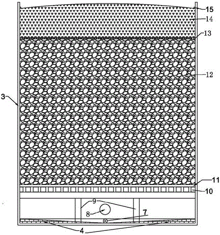
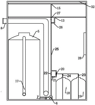
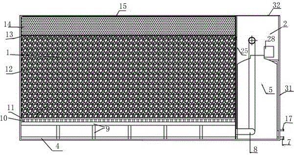
[0019] 1 biological filter filter room, 2 equipment room, 3 biological filter shell, 4 leachate slope at the bottom of the filter, 5 spray tank, 6 spray pump, 7 leachate collection pipe, 8 air intake pipe, 9 Bottom load-bearing bracket, 10 grid, 11 air distribution filter, 12 composite filler layer, 13 drip irrigation pipe, 14 top filler layer, 15 top spray pipe, 16 top sprinkler head, 17 supplementary water pipe, 18 nutrient solution tank, 19pH Value balance liquid tank, 20 Venturi mixer, 21 valve, 22 valve, 23 valve, 24 valve, 25 spray water main pipe, 26 solenoid valve, 27 solenoid valve, 28 automatic control device panel, 29 spray water inlet pipe, 30 Spray water outlet pipe, 31 cabinet door, 32 equipment room top cover

[0020] Below in conjunction with accompanying drawing, the present invention will be further described,

[0021] Depend on Figure 1-3 It can be seen that the present invention is a cuboid. The middle of the cuboid is divided into two parts by a partit...


PUM


Abstract

The invention provides a biological filter device for purifying foul gas and volatile organic compounds (VOCs). The biological filter device is mainly characterized in that the biological filter device is a cuboid; the middle of the cuboid is divided into two parts, namely a filter chamber and an equipment chamber through a separation plate; the filter chamber is composed of a bottom percolate slope face, a gas distributing system, biological filter filler and a pouring device from bottom to top, the percolate slope face is arranged at the bottom of the filter chamber and is in a V shape when seen from the side face, and a percolation pipe is arranged in the middle of the bottom of the percolate slope face to collect percolate converged on the slope face; the equipment chamber comprises a water spraying and storage tank, a nutrient solution tank, a pH value balancing liquid tank, a pipeline, a pump, a valve and an automatic control device. The biological filter device has the advantages of being small in occupied area, low in cost, capable of being moved and expanded, low in energy consumption, low in running cost, high in reliability, convenient to maintain and free of secondary pollution. Integrated and modular design is adopted, the occupied area is reduced, investment cost is reduced, the device can be moved, treatment is flexible, and running cost is reduced.

Description

technical field [0001] The invention relates to a biological treatment waste gas device, in particular to a biological filter treatment device for removing malodorous gas and high-flow low-concentration volatile organic compound VOCs. Background technique [0002] In urban sewage treatment, sludge treatment, garbage disposal, fermentation pharmaceuticals, rubber and plastics, paint coatings, printing and dyeing leather, livestock breeding, food processing, papermaking and other industrial industries produce a large amount of odorous gases and volatile organic compounds VOCs and other pollutants, which are harmful to human health and serious damage to the ecological environment. Malodorous gases can adversely affect the human respiratory system, circulatory system, digestive system, endocrine system, and nervous system. Volatile organic compounds (VOCs) not only directly endanger human health, but also are precursors of PM2.5, which is one of the main factors causing air pol...

Claims


Application Information

Patent Timeline
Patent Type & Authority Applications(China)
IPC IPC(8): B01D53/84
CPCB01D53/84B01D2251/95B01D2257/708B01D2257/90Y02A50/20
Inventor 王海英
Owner 王海英
Why Eureka
Eureka Blog
Learn More