Muffle furnace crucible frame for automatic production line and working method thereof
An automatic production line, muffle furnace technology, applied in the direction of crucible furnace, furnace, furnace type, etc., to achieve the effect of small deformation, safe use, and guaranteed use
- Summary
- Abstract
- Description
- Claims
- Application Information
AI Technical Summary
Problems solved by technology
Method used
Image
Examples
Embodiment 1
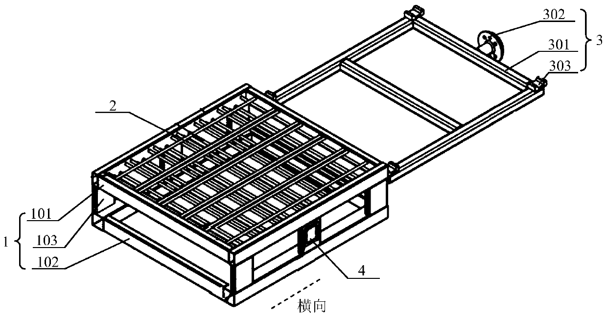
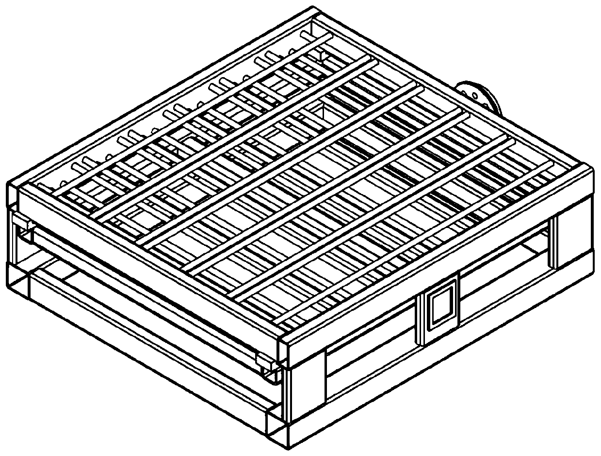
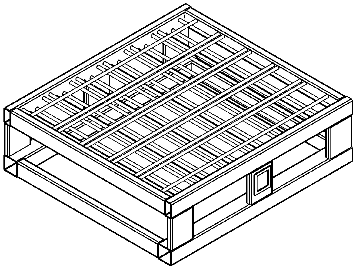
[0056] A muffle furnace crucible frame for an automated production line, such as Figure 1-8 As shown, it includes a crucible support part 1, a crucible positioning frame 2 for placing a crucible, and a manipulator bracket 3 for taking and placing a crucible frame from a muffle furnace;
[0057] Such as Figure 4 As shown, the crucible support part 1 includes an upper support frame 101, a lower support frame 102 and a standpipe 103 connecting the upper support frame 101 and the lower support frame 102, as Figure 6 As shown, the crucible positioning frame 2 is a network frame composed of a plurality of cylindrical bars, and each tubular structure in the network frame is inserted on the upper support frame 101;
[0058] Such as Figure 5 As shown, the manipulator bracket 3 includes a bracket body 301 , a flange 302 for connecting the manipulator, and a limit block 303 for limiting when the bracket body 301 is inserted into the crucible support part 1 .
Embodiment 2
[0060] A muffle furnace crucible frame for an automated production line, the structure of which is shown in Embodiment 1, the difference is that the upper support frame 101, the lower support frame 102, and the stand pipe 103 of the crucible support part 1 are all tubular structures, and the upper support The frame 101 and the lower support frame 102 are rectangular frames welded by two transverse support tubes and two vertical support tubes ( figure 1 The direction shown by the dotted line is horizontal), and the standpipe 103 is vertically welded on the two ends of the horizontal support frame of the upper support frame 101 and the lower support frame 102, that is, the manipulator bracket 3 extends horizontally into the crucible support part 1, and erects The tubes 103 are arranged at both ends of the upper support frame 101 and the lower support frame 102 , which can reserve more space for the manipulator bracket 3 .
[0061] Since the crucible frame will be reused in the m...
Embodiment 3
[0063] A muffle furnace crucible frame for an automated production line, the structure of which is shown in Embodiment 2, the difference is that the bracket body 301 of the manipulator bracket is a rectangular frame, which is used to insert the inner space of the crucible support part laterally, and the bracket body The four corners of 301 are provided with limit blocks 303, and the limit blocks 303 are positioning slots with an upward opening, which are used to be stuck on the bottom of the longitudinal support tube of the upper support frame 101;
[0064] The upward positioning slot is matched with the bottom of the longitudinal support tube of the support frame. The shape of the opening can be determined according to the bottom shape of the longitudinal support tube. In this embodiment, the opening of the positioning slot is U-shaped, corresponding to the longitudinal support tube The bottom shape is an arc structure.
PUM
| Property | Measurement | Unit |
|---|---|---|
| Yield strength | aaaaa | aaaaa |
| Yield strength | aaaaa | aaaaa |
| Maximum stress | aaaaa | aaaaa |
Abstract
Description
Claims
Application Information
 - R&D Engineer
- R&D Manager
- IP Professional
- Industry Leading Data Capabilities
- Powerful AI technology
- Patent DNA Extraction
Browse by: Latest US Patents, China's latest patents, Technical Efficacy Thesaurus, Application Domain, Technology Topic, Popular Technical Reports.
© 2024 PatSnap. All rights reserved.Legal|Privacy policy|Modern Slavery Act Transparency Statement|Sitemap|About US| Contact US: help@patsnap.com


