Eureka AIR delivers breakthrough ideas for toughest innovation challenges, trusted by R&D personnel around the world.

COD digester and application method thereof

A digester and shell technology, applied in the field of COD digesters, can solve the problems of trouble, the reflux condenser is easy to get hot, the condensation effect of the reflux condenser is deteriorated, etc., and achieves a good effect, stable condensation effect and enhanced stability. Effect

Active Publication Date: 2020-02-28
台州市绿水青山环境科技有限公司
View PDF6 Cites 4 Cited by
  • Summary
  • Abstract
  • Description
  • Claims
  • Application Information

AI Technical Summary

Problems solved by technology

[0004] During the use of the above-mentioned COD digester, the condensation is mainly carried out through the reflux condenser pipe, but after a certain period of use, the reflux condenser pipe tends to become hot, resulting in poor condensation effect of the reflux condenser pipe, which is troublesome and needs to be improved

Method used


Image

  • COD digester and application method thereof
  • COD digester and application method thereof
  • COD digester and application method thereof

Examples


Embodiment 1

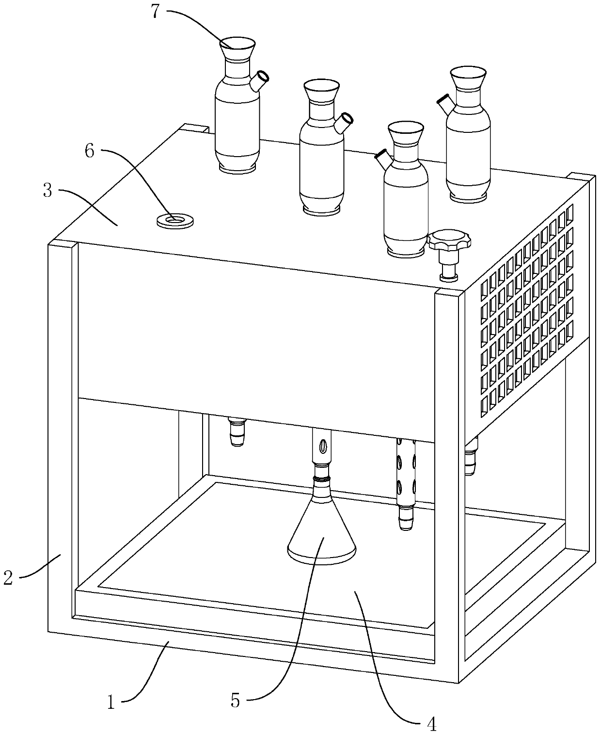
[0041] A COD digester, such as figure 1 As shown, it includes a base 1 , a bracket 2 fixed on the base 1 and a mount 3 fixed above the bracket 2 . The base 1 is provided with a heating electric furnace plate 4 on which a digestion bottle 5 is placed, and the heating electric furnace plate 4 is used to heat the digestion bottle 5 after being energized. The bracket 2 is four uprights distributed in a square shape, and the uprights are all fixedly connected to the front and rear end surfaces of the mounting seat 3 . The mounting base 3 is provided with several mounting holes 6 along the vertical direction, the mounting holes 6 are provided with a reflux condenser pipe 7 , and the lower end of the reflux condenser pipe 7 is connected with the digestion bottle 5 .

[0042] Such as figure 2 , image 3 As shown, the reflux condenser tube 7 is arranged in the shape of a circular tube, and the lower end of the reflux condenser tube 7 is tapered to facilitate insertion into the dige...

Embodiment 2

[0049] A method for using a COD digester, comprising the following steps:

[0050] S1, block the lower end of the reflux condenser pipe 7 with a plug, insert the lower end of the reflux condenser pipe 7 into the cooling liquid so that the cooling liquid is filled into the groove 11, then take out the reflux condenser pipe 7, and insert the lower end of the reflux condenser pipe 7 After the outer wall is wiped clean, remove the plug;

[0051] S2, add the liquid to be detected into the digestion bottle 5, and then put it on the heating plate 4, and then pass the reflux condenser tube 7 through the installation hole 6, so that the lower end of the reflux condenser tube 7 is inserted into the digestion bottle 5 and the digestion bottle 5 Sealed connection, the height of the lower casing 32 is adjusted by the adjustment assembly 12, so that the lower end surface of the lower casing 32 is higher than the mouth of the digestion bottle 5 within 10 mm;

[0052] S3, start heating the e...


PUM


Abstract

The invention discloses a COD digester, and relates to the field of water sample detection devices. According to the technical scheme, the digester comprises a base, a support arranged on the base anda mounting base arranged at the upper portion of the support; an electric heating furnace plate is arranged on the base; a digestion bottle is placed on the electric heating furnace plate; a plurality of mounting holes are formed in the mounting base in the vertical direction; and reflux condensing pipes are arranged on the mounting holes, the lower ends of the reflux condensing pipes are connected with the digestion bottle, the mounting base is a hollow shell, a cooling fan is arranged in the mounting base and used for blowing air to the reflux condensing pipes for cooling, and vent holes are formed in the two ends, in the air blowing direction of the cooling fan, of the mounting base. Air is blown through the cooling fan to cool the reflux condensing pipes in time, and therefore, the condensation effect of the reflux condensing pipes is more stable.

Description

technical field [0001] The invention relates to the field of water sample detection equipment, more specifically, it relates to a COD digester and its usage method. Background technique [0002] In the field of environmental protection, chemical oxygen demand (abbreviated as COD) is one of the main control indicators of surface water and wastewater, and an important comprehensive indicator of organic pollution of water. [0003] The instruments used by environmental protection monitoring agencies to detect sewage usually include COD digesters, which are mainly used to degrade difficult-to-measure substances and convert them into easily-measured compounds or ions. The COD digester is generally composed of a host, a bracket and a base. A heating electric furnace plate is installed on the base, and a digestion bottle is placed on the electric furnace board. The digestion bottle is connected to a reflux condenser. [0004] During the use of the above-mentioned COD digester, the...

Claims


Application Information

Patent Timeline
Patent Type & Authority Applications(China)
IPC IPC(8): G01N1/44H05K7/20
CPCG01N1/44H05K7/20136H05K7/20218H05K7/20345
Inventor 张犇黄仁辉王嬉巧
Owner 台州市绿水青山环境科技有限公司
Why Eureka
Eureka Blog
Learn More