High-frequency narrow pulse detection locking circuit and method

A locking circuit and narrow pulse technology, which is applied in the direction of measuring electricity, measuring electrical variables, measuring devices, etc., can solve the problems of high cost and complex detection circuit design, and achieve the effect of low cost, wide application range and high reliability

Active Publication Date: 2020-02-28
SUZHOU LANGCHAO INTELLIGENT TECH CO LTD
7 Cites 0 Cited by

AI-Extracted Technical Summary

Problems solved by technology

[0005] In the embodiment of the present invention, a high-frequency narrow pulse detection and locking circuit ...

Abstract

The embodiment of the invention discloses a high-frequency narrow pulse detection locking circuit and method. The circuit comprises a control unit, a locking and unlocking unit, a voltage division unit and a protection unit; the control unit is used for outputting a high level when the circuit detects a first high-frequency narrow pulse signal; the circuit outputs a low level when detecting a second high-frequency narrow pulse signal, the locking and unlocking unit is used for locking a first high-frequency narrow pulse signal or unlocking the first high-frequency narrow pulse signal, the voltage dividing unit is used for providing a divided voltage for the locking and unlocking unit, and the protection unit is used for overvoltage protection. According to the method, when the circuit detects the first high-frequency narrow pulse signal, the first high-frequency narrow pulse signal is locked; when the circuit detects the second high-frequency narrow pulse signal, the first high-frequency narrow pulse signal is unlocked. The high-frequency narrow pulse detection circuit adopts discrete components to detect high-frequency narrow pulses, and is simple in circuit design, high in reliability, low in cost and wide in application range.

Application Domain

Environmental/reliability tests

Technology Topic

Hemt circuitsMechanical engineering +4

Image

  • High-frequency narrow pulse detection locking circuit and method
  • High-frequency narrow pulse detection locking circuit and method
  • High-frequency narrow pulse detection locking circuit and method

Examples

  • Experimental program(1)

Example Embodiment

[0030] In order to clearly illustrate the technical features of the solution, the present invention will be described in detail below through specific embodiments and in conjunction with the accompanying drawings. The following disclosure provides many different embodiments or examples for implementing different structures of the invention. In order to simplify the disclosure of the present invention, the components and arrangements of specific examples are described below. Furthermore, the present invention may repeat reference numerals and/or letters in different instances. This repetition is for the purpose of simplicity and clarity and does not in itself indicate a relationship between the various embodiments and/or arrangements discussed. It should be noted that the components illustrated in the figures are not necessarily drawn to scale. Descriptions of well-known components and processing techniques and processes are omitted from the present invention to avoid unnecessarily limiting the present invention.
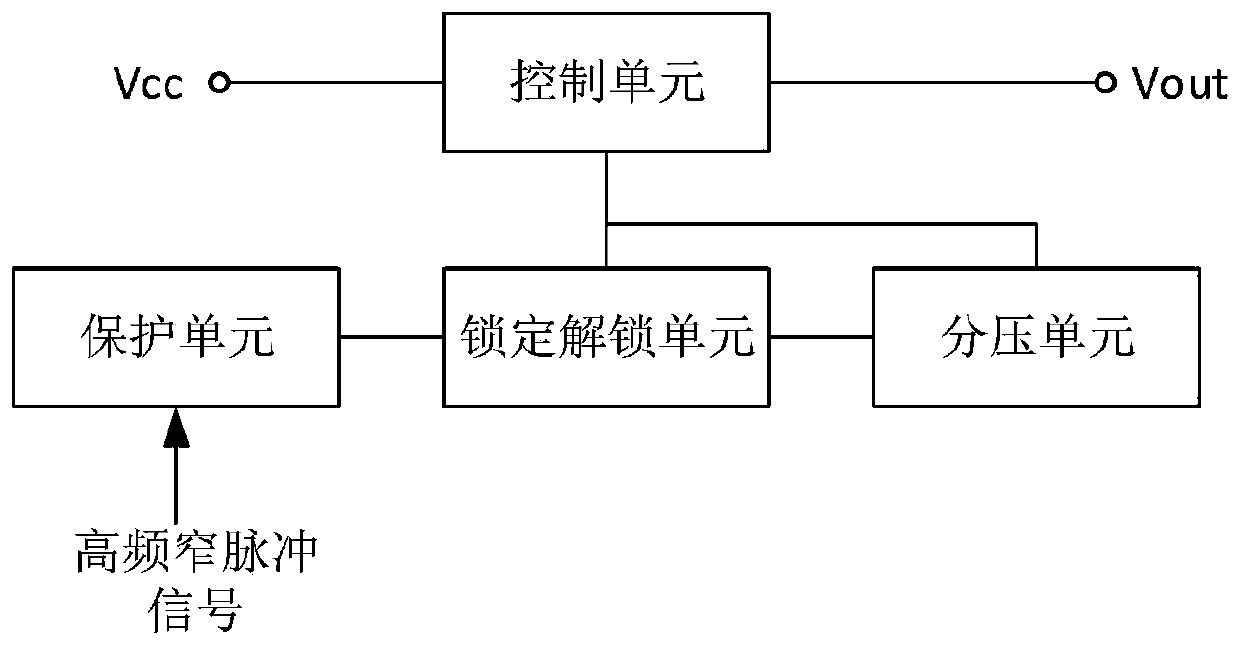
[0031] like figure 1 As shown, it is a block diagram of the circuit structure of the embodiment of the present invention. The circuit includes a control unit, a locking and unlocking unit, a voltage dividing unit and a protection unit. The control unit is connected to the locking and unlocking unit and the voltage dividing unit, and the protection unit is connected to the locking and unlocking unit. The control unit is used to output a high level when the circuit detects the first high-frequency narrow pulse signal, output a low level when the circuit detects the second high-frequency narrow pulse signal, and the locking and unlocking unit is used to lock the first high-frequency narrow pulse signal or unlocking the first high-frequency narrow pulse signal, the voltage dividing unit is used to provide voltage dividing for the locking and unlocking unit, and the protection unit is used for overvoltage protection.
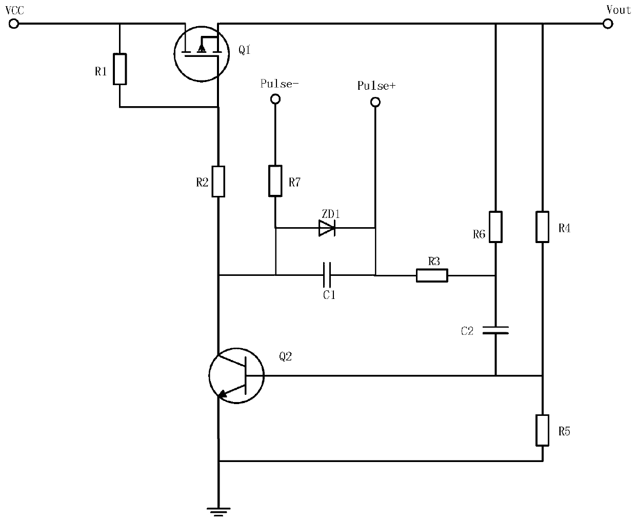
[0032] like figure 2 As shown, it is a circuit schematic diagram of an embodiment of the present invention.
[0033] The control unit includes a P-type MOSFET transistor Q1, a resistor R1 and a resistor R2, the gate of the P-type MOSFET transistor Q1 is connected to one end of the resistor R1 and one end of the resistor R2, and the source of the P-type MOSFET transistor Q1 is connected to the other end of the resistor R1 and Vcc , the drain of the P-type MOSFET transistor Q1 is connected to the output voltage Vout and one end of the resistor R6.
[0034] In the embodiment of the present invention, the type of the P-type MOSFET transistor Q1 is IRFR5305, the absolute value of the rated voltage of VGS is less than 5V, and other PMOS transistors that meet this requirement can also be used.
[0035] The locking and unlocking unit includes an NPN transistor Q2, a resistor R3, a resistor R6, a capacitor C1 and a capacitor C2. The collector of the NPN transistor Q2 is connected to the other end of the resistor R2 and one end of the capacitor C1, and the base of the NPN transistor Q2 is connected to one end of the capacitor C2 and One end of the resistor R5, the emitter of the NPN transistor Q2 is grounded, the other end of the capacitor C2 is connected to one end of the resistor R3 and the other end of the resistor R6, and the other end of the resistor R3 is connected to the other end of the capacitor C1.
[0036] In the embodiment of the present invention, the model of the NPN transistor Q2 is S8050 (the turn-on voltage is 0.7V). In the schematic diagram of this embodiment, the base voltage of Q2 is about 0.9V, and other low-power transistors that meet the turn-on voltage of less than 0.9V , can be used.
[0037] The voltage dividing unit includes a resistor R4, one end of the resistor R4 is connected to Vout, the other end of the resistor R4 is connected to one end of the resistor R5 and one end of the capacitor C2, and the other end of the resistor R5 is grounded; the resistor R4 and the resistor R5 are connected in series, and the resistor R5 is used to supply the NPN The base of transistor Q2 provides the second divided voltage.
[0038] The protection unit includes a voltage regulator tube ZD1 and a resistor R7. The positive electrode of the voltage regulator tube ZD1 is connected to one end of the resistor R7 and one end of the capacitor C1. The negative electrode of the voltage regulator tube ZD1 is connected to the other end of the capacitor C1 and the positive input end of the high-frequency narrow pulse. The other end of the resistor R7 is connected to the negative input end of the high-frequency narrow pulse; the Zener tube ZD1 is used for overvoltage protection to prevent the noise voltage from being too large and damaging the subsequent components, and the resistor R7 is used for current limiting.
[0039] The voltage regulator tube ZD1 used in the embodiment of the present invention is IN4733, the voltage regulator value is 5.1V, and the voltage regulator value is less than the rated value of the capacitor C1. Other voltage regulator tubes that meet this requirement can also be selected.
[0040] The working principle of the circuit of the embodiment of the present invention is:
[0041] When the circuit is powered on and no high-frequency narrow pulse signal is detected, the VGS of the P-type MOSFET transistor Q1 does not reach the turn-on voltage, the P-type MOSFET transistor Q1 is turned off, the base of the NPN transistor Q2 is turned off without voltage division, and the output voltage Vout output low level;
[0042] When the circuit detects the first high-frequency narrow pulse signal, the capacitor C1 is turned on instantly, and then, C2 is also quickly turned on. The capacitor C1 and the capacitor C2 are equivalent to a wire. The power supply Vcc passes through the resistor R1, the resistor R2, and the capacitor C1. , resistor R3, capacitor C2, and resistor R5 are turned on, the base of NPN transistor Q2 gets the first voltage divider, and NPN transistor Q2 is instantly turned on. At this time, the gate voltage of P-type MOSFET transistor Q1 becomes 0, P-type The MOSFET Q1 is turned on instantly, and the output voltage Vout outputs a high level. At this time, the resistor R4 and the resistor R5 are connected in parallel. The resistor R5 provides a second voltage divider for the base of the NPN transistor Q2, and the NPN transistor Q2 and the P-type MOSFET transistor Q1 maintain conduction. In the on state, the output voltage Vout continues to output a high level, that is, the first high-frequency narrow pulse signal is locked;
[0043] When the circuit detects the second high-frequency narrow pulse signal, the second divided voltage of the base of the NPN transistor Q2 is rapidly discharged through the collector of the NPN transistor Q2, the capacitor C1, the resistor R3 and the capacitor C2, and the base of the NPN transistor Q2 is rapidly discharged. The voltage drop is cut off instantly, the gate voltage of the P-type MOSFET transistor Q1 is restored to Vcc, the P-type MOSFET transistor Q1 is turned off, and the output voltage Vout continues to output a low level, that is, the first high-frequency narrow pulse signal is unlocked.
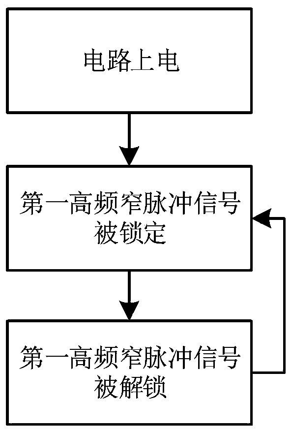
[0044] like image 3 As shown, it is a flowchart of the method according to the embodiment of the present invention, which specifically includes:
[0045] When the circuit is powered on and no high-frequency narrow pulse signal is detected, the P-type MOSFET transistor Q1 and the NPN transistor Q2 are turned off, and the output voltage Vout outputs a low level;
[0046] When the circuit detects the first high frequency narrow pulse signal, the first high frequency narrow pulse signal is locked;
[0047] When the circuit detects the second high frequency narrow pulse signal, the first high frequency narrow pulse signal is unlocked.
[0048] The process of locking the first high-frequency narrow pulse signal is as follows:
[0049] When the circuit detects the first high-frequency narrow pulse signal, the capacitor C1 is turned on instantly, and then, C2 is also quickly turned on. The capacitor C1 and the capacitor C2 are equivalent to a wire. The power supply Vcc passes through the resistor R1, the resistor R2, and the capacitor C1. , resistor R3, capacitor C2, and resistor R5 are turned on, the base of NPN transistor Q2 gets the first voltage divider, and NPN transistor Q2 is instantly turned on. At this time, the gate voltage of P-type MOSFET transistor Q1 becomes 0, P-type The MOSFET Q1 is turned on instantly, and the output voltage Vout outputs a high level. At this time, the resistor R4 and the resistor R5 are connected in parallel. The resistor R5 provides a second voltage divider for the base of the NPN transistor Q2, and the NPN transistor Q2 and the P-type MOSFET transistor Q1 maintain conduction. In the on state, the output voltage Vout continues to output a high level.
[0050] The process of unlocking the first high-frequency narrow pulse signal is as follows:
[0051] When the circuit detects the second high-frequency narrow pulse signal, the second divided voltage of the base of the NPN transistor Q2 is rapidly discharged through the collector of the NPN transistor Q2, the capacitor C1, the resistor R3 and the capacitor C2, and the base of the NPN transistor Q2 is rapidly discharged. The voltage drop is cut off instantly, the gate voltage of the P-type MOSFET transistor Q1 is restored to Vcc, the P-type MOSFET transistor Q1 is turned off, and the output voltage Vout continues to output a low level.
[0052] If multiple groups of high-frequency narrow pulse signals are detected during the operation of the circuit, the process of locking and unlocking the high-frequency narrow pulse signals will be repeated until the circuit stops working.
[0053] The above are only the preferred embodiments of the present invention. For those skilled in the art, without departing from the principles of the present invention, several improvements and modifications can be made, and these improvements and modifications are also regarded as the present invention. The scope of protection of the invention.

PUM

no PUM

Description & Claims & Application Information

We can also present the details of the Description, Claims and Application information to help users get a comprehensive understanding of the technical details of the patent, such as background art, summary of invention, brief description of drawings, description of embodiments, and other original content. On the other hand, users can also determine the specific scope of protection of the technology through the list of claims; as well as understand the changes in the life cycle of the technology with the presentation of the patent timeline. Login to view more.

Similar technology patents

Load balancing method and system applied to distributed application system

InactiveCN102123179AEnsure balanced distributionImprove reliability
Owner:NAT UNIV OF DEFENSE TECH

Hybrid excitation E-shaped iron core axial magnetic field permanent magnet brushless motor

InactiveCN102223036AImprove reliabilityTo achieve fault-tolerant operation
Owner:SOUTHEAST UNIV

Classification and recommendation of technical efficacy words

  • Improve reliability
  • low cost

Organic light emitting diode display

ActiveUS20070008268A1improve reliability
Owner:LG DISPLAY CO LTD

Method and apparatus for correcting errors in memory device

ActiveUS20120151294A1improve reliability
Owner:SAMSUNG ELECTRONICS CO LTD

Multiple branch predictions

ActiveUS20050268075A1improve reliabilityfacilitate availability
Owner:ORACLE INT CORP

System and method for transmitting wireless digital service signals via power transmission lines

ActiveUS7929940B1reduce bandwidth requirementlow cost
Owner:NEXTEL COMMUNICATIONS

Plastic waveguide-fed horn antenna

InactiveUS20100214185A1low cost
Owner:RGT UNIV OF CALIFORNIA

System and method for determination of position

InactiveUS20090149202A1low costreduce requirement
Owner:STEELE CHRISTIAN

Adaptive antenna optimization network

InactiveUS6961368B2low costminimal space
Owner:ERICSSON INC
Why Eureka
Try Eureka