Target reflectivity distribution resolving method of laser reflection tomography

A technology of tomography and laser reflection, applied in the direction of using re-radiation, re-radiation of electromagnetic waves, measuring devices, etc., can solve the problems of waveform broadening, pulse peak reduction, and reconstruction image resolution reduction, so as to reduce the impact and achieve rapid and effective formation. , the effect of improving image resolution

Inactive Publication Date: 2020-02-28
NAT UNIV OF DEFENSE TECH
View PDF10 Cites 1 Cited by
  • Summary
  • Abstract
  • Description
  • Claims
  • Application Information

AI Technical Summary

Problems solved by technology

This convolution effect will cause waveform broadening and pulse peak reduction in the time domain of the receive

Method used


Image

  • Target reflectivity distribution resolving method of laser reflection tomography
  • Target reflectivity distribution resolving method of laser reflection tomography
  • Target reflectivity distribution resolving method of laser reflection tomography

Examples


Embodiment Construction

[0033] In order to better understand the present invention, the present invention will be further described below in conjunction with the examples and accompanying drawings, and the following examples are only to illustrate the present invention rather than limit it.

[0034] A laser reflection tomography target reflectivity distribution solution method, such as Figure 6 shown, including the following steps:

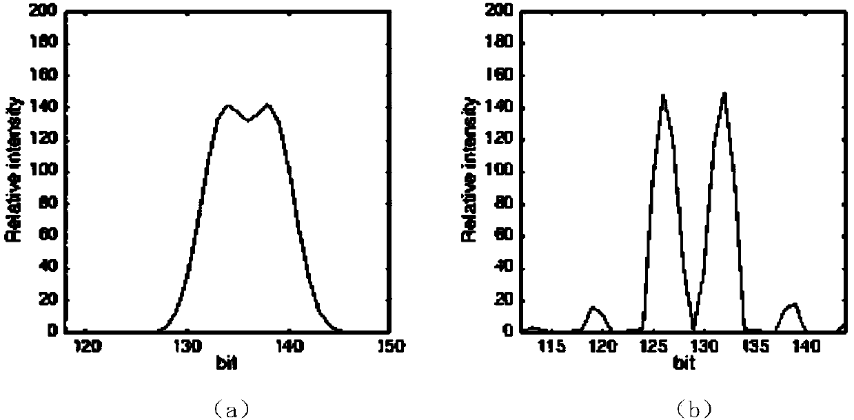
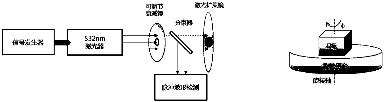
[0035] 1. The laser emits a laser beam with a Gaussian pulse waveform in the pulse. The laser pulse is modulated by a signal generator at the transmitting end. After the emitted beam passes through an adjustable attenuation mirror, the beam is split by a beam splitter, and one of the beams is detected. The detector detects and records the pulse waveform, and the other beam is expanded by the beam expander and pointed to the target (a polygonal model). The target body is completely covered by the laser spot, as shown in figure 1 shown.

[0036] 2. The target body refle...


PUM


Abstract

The invention relates to the technical field of laser reflection tomography. According to a target reflectivity distribution resolving method in the laser reflection tomography process, when the widthof emitted laser pulses is larger than a sampling period and adjacent distance samples of an effective reflection part on the surface of an object are overlapped, echo data form convolution of a reflectivity projection distribution function and laser emission pulses; an iterative maximum likelihood estimation method is adopted to deconvolve reflection echo data, under the condition that a convolution kernel is known, a parameter estimation method is used for estimating a deconvolution solution; and finally, a reflectivity distribution function of a detection target is extracted, and the precision of a laser reflection fault reconstructed image is improved. The method can effectively obtain an optimal estimator of the reflectivity distribution of the target surface, so that the pulse widthof the echo is compressed, the image resolution in a laser reflection tomography image reconstruction link is improved, influence caused by pulse broadening is reduced, and the high-precision tomography image can be formed more quickly and effectively.

Description

technical field [0001] The invention relates to the technical field of laser reflective tomography (Laser Reflective Tomography, LRT for short), in particular to the application of calculating target reflectivity distribution in the process of laser reflective tomography. Background technique [0002] In military, aerospace, remote sensing and many other fields, in order to complete tasks such as observation, identification, reconnaissance, and tracking of long-distance targets, it is necessary to obtain high-resolution images of targets at long distances. The imaging resolution of traditional optical imaging technology is limited by the diffraction limit of the system itself, and the imaging aperture of the system cannot be increased infinitely, so it is not fully competent. New long-distance, high-resolution imaging techniques have become a strong demand. Laser reflection tomography based on distance resolution is a new type of LiDAR imaging system that takes into account...

Claims


Application Information

Patent Timeline
IPC IPC(8): G01S17/89
CPCG01S17/89
Inventor 胡以华赵楠翔杨彪谷雨石亮徐世龙王金诚王勇杨星
Owner NAT UNIV OF DEFENSE TECH
Why Eureka
Try Eureka