Negative refraction photonic crystal lens

Inactive Publication Date: 2010-07-01
IND TECH RES INST
View PDF17 Cites 4 Cited by
  • Summary
  • Abstract
  • Description
  • Claims
  • Application Information

AI Technical Summary

Benefits of technology

[0008]The present invention is further directed to provide a negative refractive photonic crystal lens, adapted for improving an imaging resolution thereof up to 0.349 λ, wherein λ is the wavelength of a measuring light. Such a negative refractive photonic crystal lens is an optical lens having the highest imaging resolution at present.
[0009]The present invention provides a negative refraction photonic crystal lens. The negative refraction photonic crystal lens includes a substrate having a plurality of voids periodically distributed in the substrate. The voids are configured longitudinally extending along a direction perpendicular with an incident direction of a light having a specific wavelength. By selecting a refractive index of the substrate, a radius of the voids, and a lattice parameter of the voids, the negative refraction photonic crystal lens presents a negative refraction characteristic with respect to the specific wavelength, in that the light incident from one side of the substrate can be focused at the other side of the substrate, thus configuring an optical lens.
[0010]The present invention further provides a negative refraction photonic crystal lens. The negative refraction photonic crystal lens includes an anisotropi

Problems solved by technology

During the fabrication processes of the products, even very tiny processing defects or contaminants may seriously destroy the yield and performance of the products.
Particularly, very low defect density may negatively affect subsequent processing stages and cause incurable damage to the quality of an epitaxial wafer or an FPD substrate.
However, they are often expans

Method used


Image

  • Negative refraction photonic crystal lens
  • Negative refraction photonic crystal lens
  • Negative refraction photonic crystal lens

Examples


Example

[0021]Reference will now be made in detail to the present preferred embodiments of the invention, examples of which are illustrated in the accompanying drawings. Wherever possible, the same reference numbers are used in the drawings and the description to refer to the same or like parts.

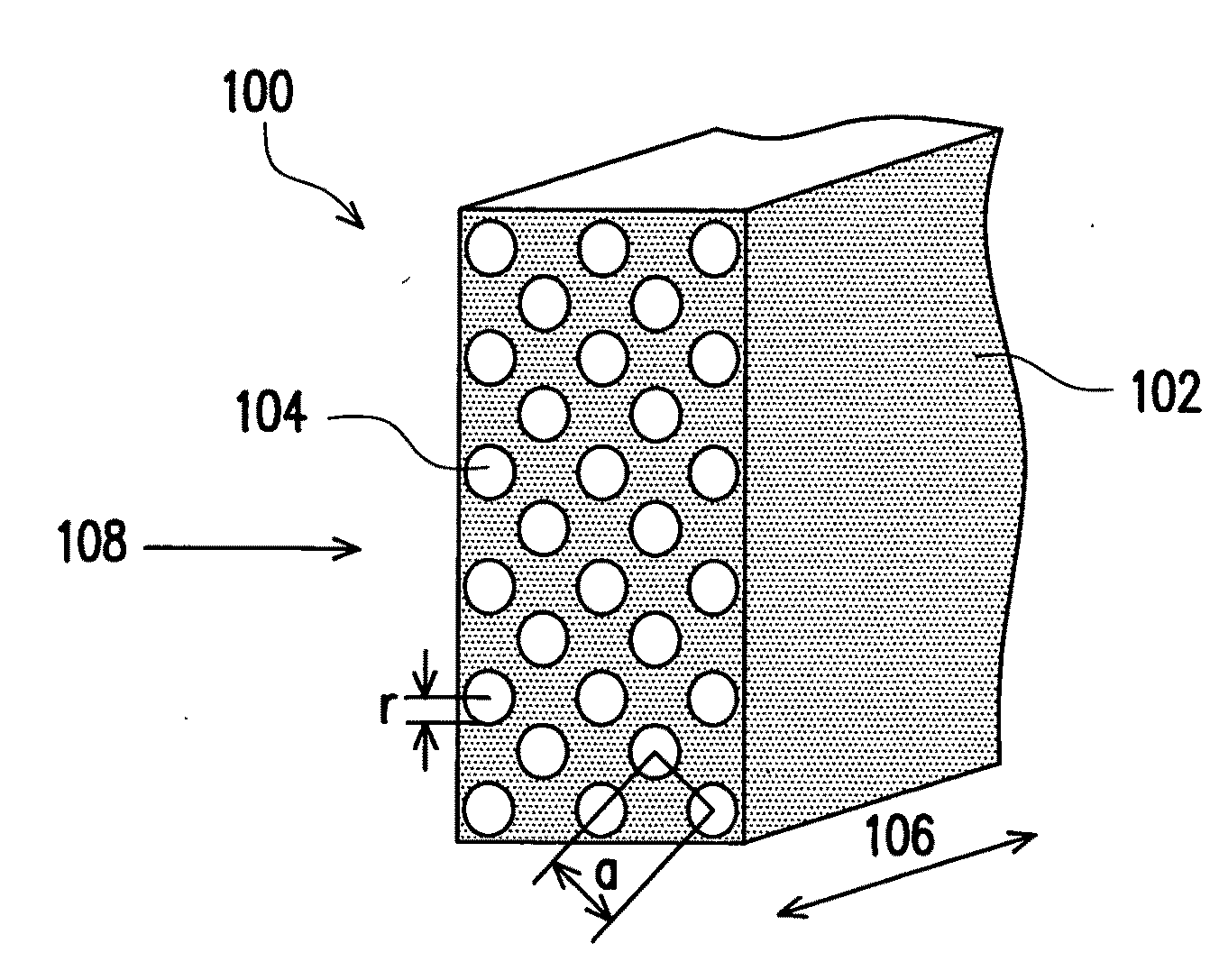
[0022]Photonic crystal is also known as a periodic structure. The discovery of the photonic crystal raises many novel theoretical and experimental research subjects. For example, a photonic structure is periodically arranged in an electromagnetic wavelength scale. An electromagnetic wave transmitted in such a photonic structure will be affected by the arrangement period, the spatial structure, and the dielectric constant of the medium. As such, the optical waveguide characteristic of the photonic structure can be designed as expected in the electromagnetic wavelength scale. In accordance with photonic energy band and the dispersion relationship between the photonic frequency and the wave vector, the ...


PUM


Abstract

A negative refraction photonic crystal lens is provided. The negative refraction photonic crystal lens includes a substrate and a plurality of voids periodically distributed in the substrate. The voids are configured extending along a direction longitudinally perpendicular with an incident direction of a light having a specific wavelength. By suitably selecting a refractive index of the substrate, a radius of the voids, and a lattice parameter of the voids, the negative refraction photonic crystal lens presents a negative refraction characteristic with respect to the specific wavelength, in that the light incident from one side of the substrate can be focused at the other side of the substrate, thus configuring an optical lens. The optical lens is adapted for not only achieving an optimal sub-wavelength focusing performance, but also further improving the imaging resolution of the negative refraction photonic crystal lens by employing an anisotropic material for preparing the substrate.

Description

CROSS-REFERENCE TO RELATED APPLICATION[0001]This application claims the priority benefit of Taiwan application serial no. 97151428, filed on Dec. 30, 2008. The entirety of the above-mentioned patent application is hereby incorporated by reference herein and made a part of this specification.BACKGROUND OF THE INVENTION[0002]1. Field of the Invention[0003]The present invention relates to a negative refraction photonic crystal lens designed in accordance with the negative refraction characteristic of a photonic crystal structure.[0004]2. Description of Related Art[0005]In accordance with the progresses of high-tech industries and for the purpose of improving efficiencies and qualities of products, processes for fabricating the products are developed toward miniaturization. For example, all of the 30 nm and 45 nm linewidth processing of the semiconductor industry, tiny defects on the panel surface of the flat panel display (FPD) industry, and surface defects of the precision optical ele...

Claims


Application Information

Patent Timeline
IPC IPC(8): G02B3/02G02B1/02
CPCB82Y20/00G02B1/005G02B1/007G02B3/00G02B2207/107
Inventor LIU, CHENG-YANG
Owner IND TECH RES INST
Why Eureka
Try Eureka