Vibration suppression method of motor control device and device thereof

A technology of motor control and vibration suppression, applied in the direction of suppressing motor vibration control, etc., can solve the problems of reducing servo vibration amplitude, slow response of servo control, reducing equipment resonance, etc., to improve applicability and control performance, and increase servo gain ratio and rigidity, vibration suppression effect

Active Publication Date: 2020-02-28
上海新时达机器人有限公司
View PDF4 Cites 1 Cited by
  • Summary
  • Abstract
  • Description
  • Claims
  • Application Information

AI Technical Summary

Problems solved by technology

[0004] 1. Reduce the servo gain ratio, rigidity and other parameters, weaken the vibration amplitude of the servo, thereby reducing the resonance of the equipment, this method will cause the servo control to respond slowly, thereby reducing the efficiency, and cannot achieve high-precision and high-response control of the servo;
[0005] 2. Find the vibration frequency, set the frequency vibration point, avoid this frequency, and prevent the equipment driven by the motor from running at this frequency. Operation at the frequency of the frequency point, so that the operation at the full frequency point cannot be realized;
This method will cause a delay in the torque response in the servo control, resulting in the inability to achieve high-response control

Method used


Image

  • Vibration suppression method of motor control device and device thereof
  • Vibration suppression method of motor control device and device thereof
  • Vibration suppression method of motor control device and device thereof

Examples


Embodiment Construction

[0026] The present invention will be described in detail below in conjunction with the accompanying drawings and specific embodiments.

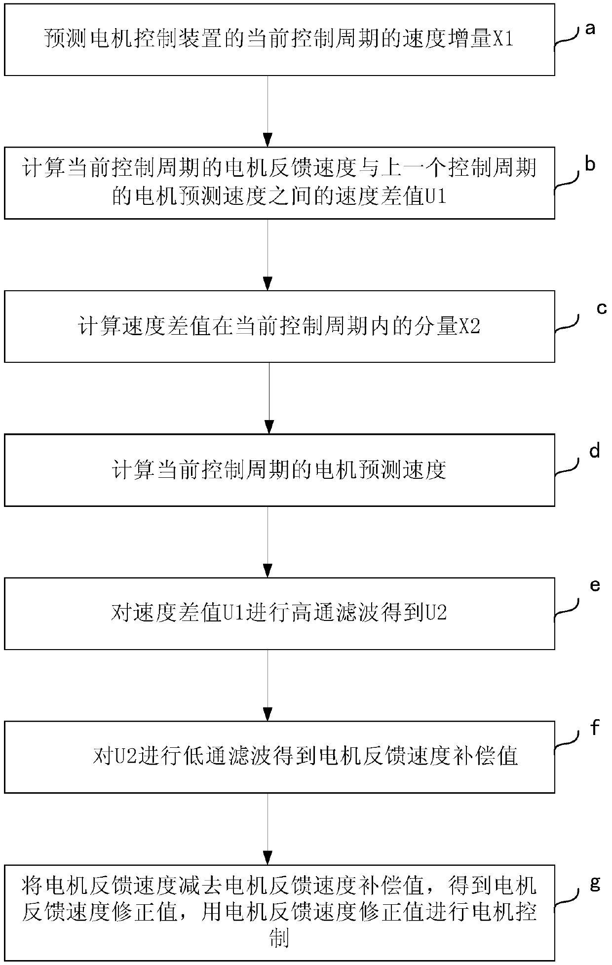
[0027] see figure 1 . A vibration suppression method for a motor control device according to an embodiment of the present invention includes the following steps:

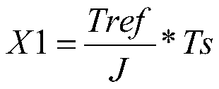
[0028] a. When controlling the motor, predict the speed increment X1 of the current control cycle of the motor control device according to the current given torque Tref and the total inertia J of the servo motor:

[0029]

[0030] Among them, Ts is the control cycle of the motor control device; the total motor inertia J is the sum of the motor inertia and the load inertia of the load driven by the motor;

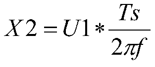
[0031] b. Calculate the speed difference U1 between the motor feedback speed Vfbk of the current control cycle and the motor predicted speed Vobs′ of the previous control cycle:

[0032] U1=Vfbk-Vobs'

[0033] The motor feedback speed Vfbk can be obtained by detecting the ...


PUM


Abstract

A vibration suppression method of a motor control device comprises the following steps: a, predicting speed increment X1 of a motor control device in the current control period according to a currently given torque and a total inertia of a servo motor; b, calculating the speed difference U1 between feedback speed of the motor and predicted speed of the motor in the previous control period; c, calculating the component X2 of the speed difference U1 in the current control period; d, calculating the predicted speed of the motor in the current control period; e, performing high-pass filtering on the speed difference U1 to obtain U2; f, performing low-pass filtering on the U2 to obtain a motor feedback speed compensation value; and g, subtracting the motor feedback speed compensation value fromthe motor feedback speed to obtain a motor feedback speed correction value, and performing motor control by using the motor feedback speed correction value. The invention also provides a motor control device. Vibration reduction control of the motor can be realized on the premise of ensuring full frequency section operation of the motor and fast response speed.

Description

technical field [0001] The invention relates to the motor control technology, in particular to the vibration suppression technology of the motor control device. Background technique [0002] With the development of automation control, the use of automation equipment is getting higher and higher. In some cases, due to problems in equipment installation, design, and stiffness, the natural frequency of the equipment will be close to the operating frequency range of the motor, resulting in noise or resonance between the motor and the equipment during operation, which will affect the performance of the equipment. normal operation. In order to reduce the resonance phenomenon generated during the motor control process and improve the operating performance of the equipment, the vibration suppression of the motor control device is required. [0003] In the prior art, there are several ways to reduce resonance: [0004] 1. Reduce the servo gain ratio, rigidity and other parameters,...

Claims


Application Information

Patent Timeline
Patent Type & Authority Applications(China)
IPC IPC(8): H02P23/04
CPCH02P23/04
Inventor 李虎修丁信忠储诚兵陈攀董平刘国华
Owner 上海新时达机器人有限公司
Why Eureka
Try Eureka