
Ball plug retention for slewing ring bearing

A ball plug and bearing technology, applied in the field of wind turbines, can solve problems such as increasing stress concentration areas

Active Publication Date: 2020-03-03
GENERAL ELECTRIC CO
View PDF7 Cites 0 Cited by
  • Summary
  • Abstract
  • Description
  • Claims
  • Application Information

AI Technical Summary

Problems solved by technology

Sometimes the tapered pin(s) can lead to areas of increased stress concentration

Method used


Image

  • Ball plug retention for slewing ring bearing
  • Ball plug retention for slewing ring bearing
  • Ball plug retention for slewing ring bearing

Examples


Embodiment Construction

[0051] Reference will now be made in detail to embodiments of the present disclosure, one or more examples of which are illustrated in the drawings. Each example is offered by way of explanation of the disclosure, not limitation of the disclosure. In fact, it will be apparent to those skilled in the art that various modifications and variations can be made in the present disclosure without departing from the scope or spirit of the disclosure. For example, features illustrated or described as part of one embodiment can be used with another embodiment to yield a still further embodiment. Thus, it is intended that the present disclosure cover such improvements and modifications as come within the scope of the appended claims and their equivalents.

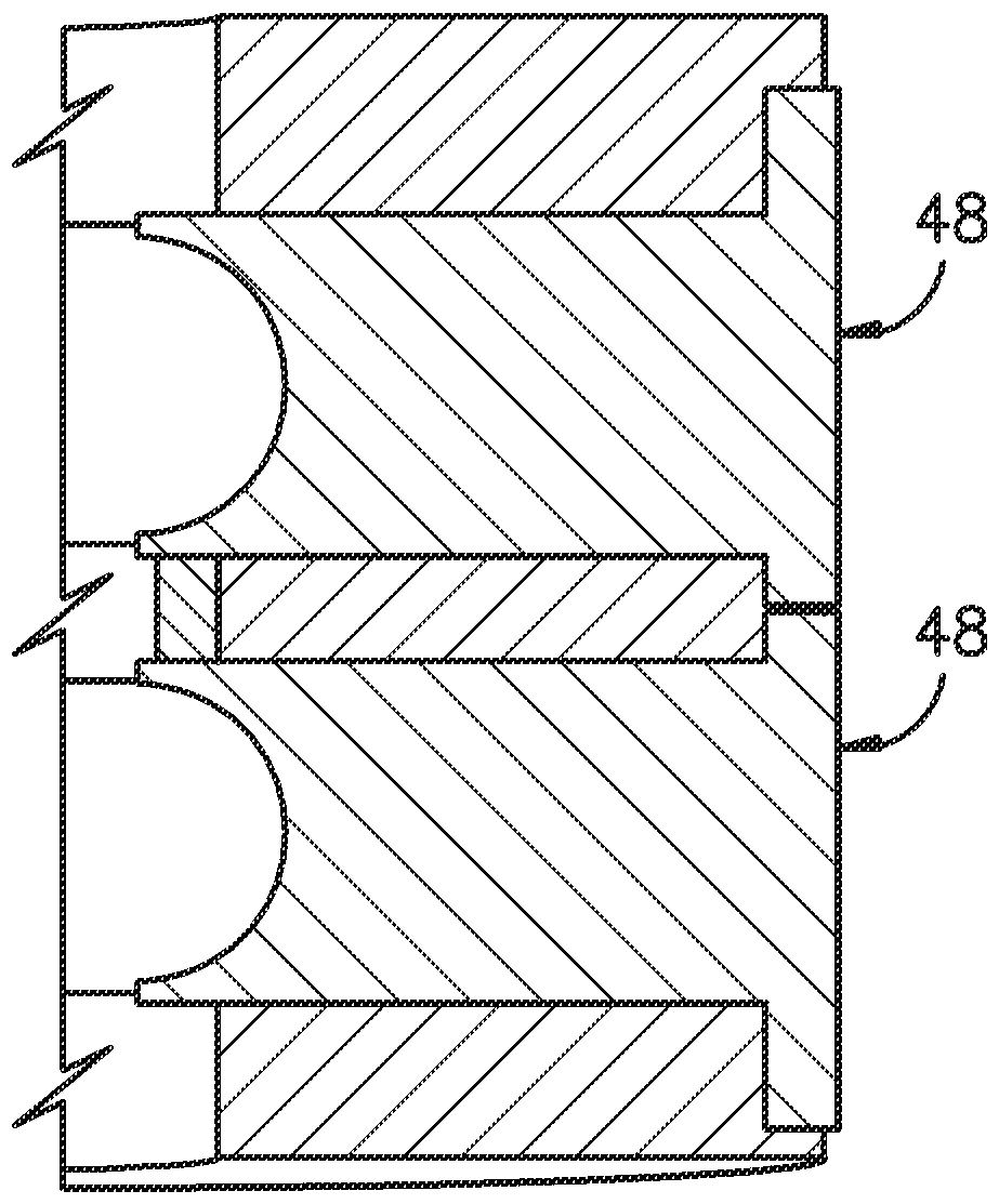
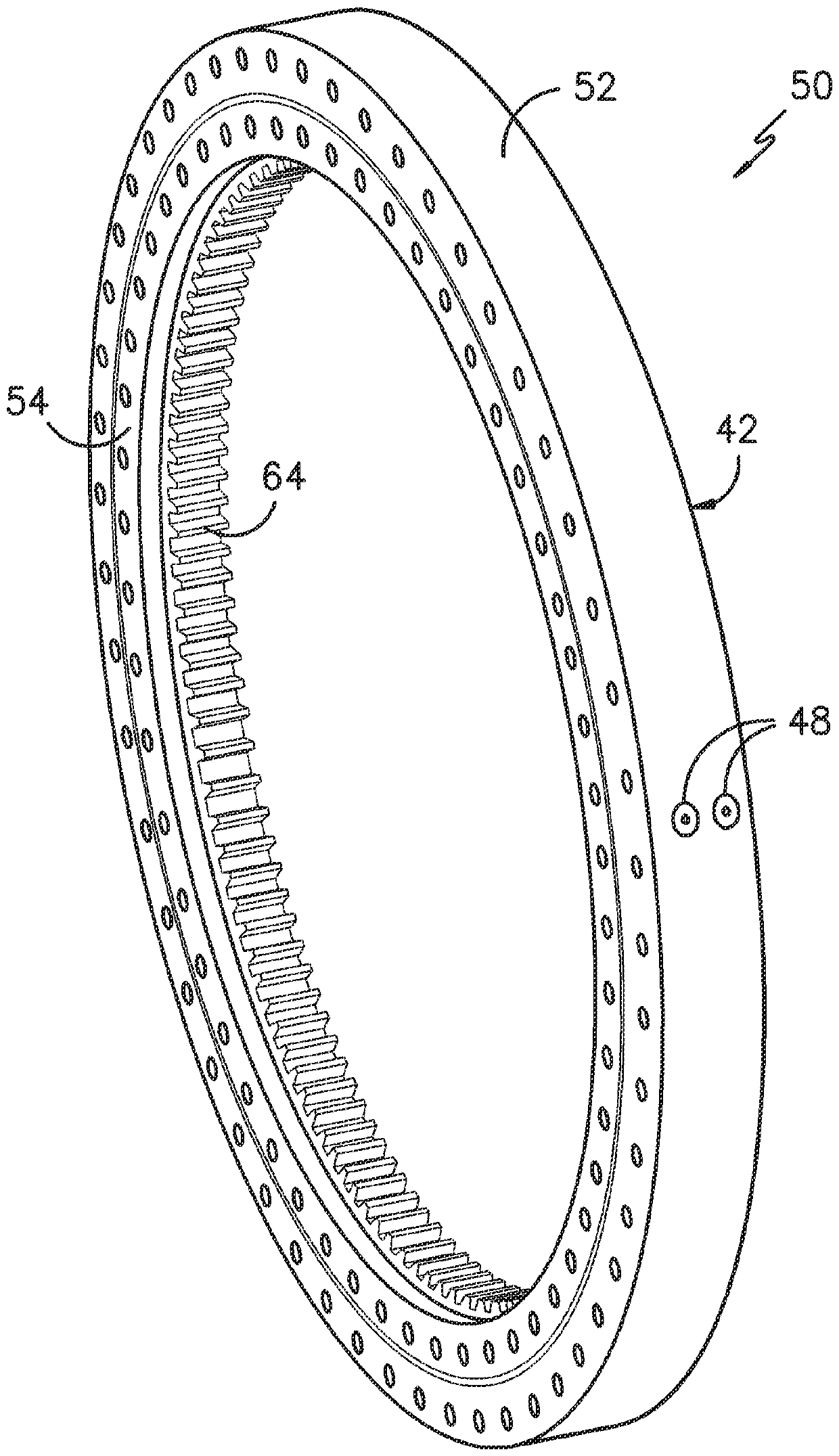
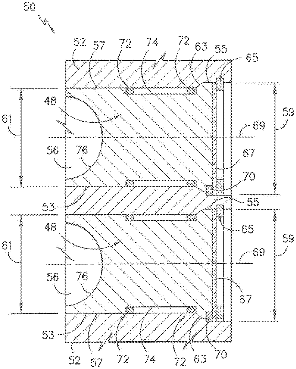
[0052] In general, the present subject matter is directed to a bearing assembly for a wind turbine that eliminates the conventional tapered pins described herein. More particularly, a taper can be introduced in the bearing to retain...


PUM


Abstract

A bearing assembly for a wind turbine includes a bearing comprising an outer race, an inner race rotatable relative to the outer race, and a plurality of roller elements positioned within at least oneraceway defined between the outer and inner races. Further, at least one of the outer race or the inner race defines a radial opening. The bearing assembly also includes at least one ball plug positioned within the radial opening of at least one of the outer race or the inner race. The ball plug(s) is removable such that the plurality of roller elements can be inserted between the outer and innerraces. Moreover, at least a portion of the ball plug(s) has a tapered cross-section.

Description

technical field [0001] The subject matter relates generally to wind turbines, and more particularly to ball plunger retention for slewing ring bearings, such as pitch or yaw bearings of wind turbines. Background technique [0002] Wind power is considered to be one of the cleanest, most environmentally friendly energy sources currently available, and in this regard, wind turbines are receiving increasing attention. A modern wind turbine typically includes a tower, generator, gearbox, nacelle, and one or more rotor blades. The rotor blades gain kinetic energy from the wind using known airfoil principles and transfer the kinetic energy as rotational energy to turn a shaft which couples the rotor blades to a gearbox or, if a gearbox is not used, directly to a generator. The generator then converts the mechanical energy into electrical energy, which can be deployed to the utility grid. [0003] To properly orient the nacelle and rotor blades relative to the direction of the wi...

Claims


Application Information

Patent Timeline
Patent Type & Authority Applications(China)
IPC IPC(8): F16C33/30F03D80/70F03D80/00
CPCF16C33/30F03D80/70F03D80/00F16C2360/31F16C19/181F16C33/585F16C33/586F16C43/06F16C2226/36F16C2226/40F16C2226/74F16C2300/14F05B2240/50F05B2260/79Y02E10/72F16C33/581F16C33/583F16C19/18
Inventor D.C.帕图沃思A.D.米纳德奥W.M.戈贝利
Owner GENERAL ELECTRIC CO
Learn More