
Patsnap Eureka
For R&D, Patsnap Eureka makes reading and utilizing patents & technical documents easy.
Patsnap Eureka AIR
Designed for self-driven R&D workflows. Generate viable solutions, solve complex R&D challenges, empower your innovation with AI.

Patsnap Eureka Materials
Designed for material experts only. Revolutionize your material R&D, from search, analyze, to developing new materials.

TechResearch
Generate reliable direction feasibility study reports for your R&D in just a few steps.

TechSeek
Discover and master advanced knowledge NOW. Basics, ideas, possibilities, all at once.

TechMind
As an expert in R&D Theories, TechMind can generates customized viable solutions instantly.

TechRisk
Analyze your overall solution with one click, know your potential R&D risks in advance.

TechMonitor
Get weekly tech updates, stay abreast of the latest tech innovations and key insights.
Pipe drawing machine for centrifugal pouring equipment of nodular cast iron pipe
A nodular cast iron pipe, centrifugal casting technology, applied in the field of casting, can solve the problems of inconvenient use, complicated operation, etc., and achieve the effect of convenient operation, reasonable and simple structure, and stable structure
- Summary
- Abstract
- Description
- Claims
- Application Information
AI Technical Summary
Problems solved by technology
Method used
Image

Examples
Embodiment 1
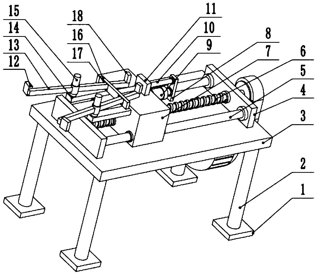
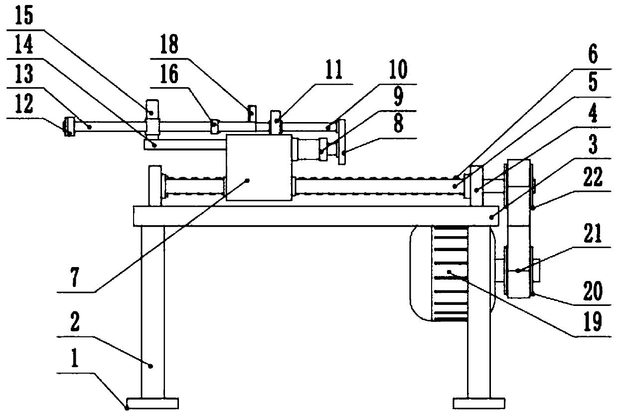
[0024] see Figure 1-3 , a pipe pulling machine for centrifugal casting equipment for ductile iron pipes, including a workbench 3, four corners of the lower surface of the workbench 3 are provided with support columns 2, and the lower end of the support column 2 is provided with pads 1, pads Block 1 can increase the distance between the device and the ground, so that the device can be placed on the installation ground more stably. The upper surface of the workbench 3 is provided with fixed plates 4 on the left and right sides, and the front and rear sides of the fixed plate 4 are provided with guides. Rod 5, the middle part of guide rod 5 is slidingly connected with fixed seat 7, and the middle part of described fixed plate 4 is rotated and connected with screw mandrel 6, and the middle part of screw mandrel 6 is screwed with the middle part of fixed seat 7, and the lower surface right side of workbench 3 is provided with Drive motor 19, the output shaft of drive motor 19 is f...
Embodiment 2
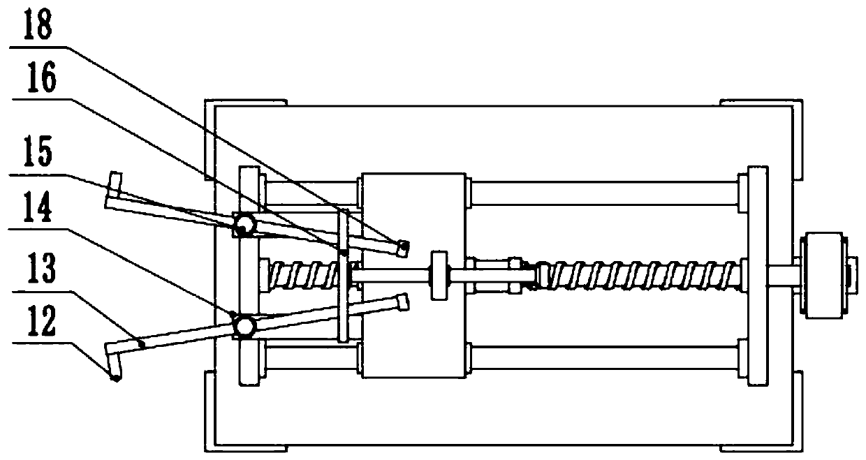
[0027] Other contents of this embodiment are the same as those of Embodiment 1, except that the top block 12 is made of rubber. The use of the top block 12 made of rubber can avoid the rigid contact between the top block 12 and the inner wall of the pipeline, resulting in damage to the pipeline. At the same time, the deformation of the rubber material itself can increase the friction between the left end of the rotating rod 13 and the inner wall of the pipeline, so that the pipeline can be Pulled out more stably.
[0028] During the implementation of the present invention, the device is placed on the right end of the cast iron that needs to be pulled out of the pipeline, the hydraulic cylinder 9 is activated, and the piston rod of the hydraulic cylinder 9 shrinks, thereby driving the sliding rod 10 to move to the left through the baffle plate 8, so that The spacing of two rotating rods 13 left ends reduces, starts drive motor 19 now, and the output shaft of drive motor 19 driv...
PUM
 Abstract
Description
Claims
Application Information
 - R&D Engineer
- R&D Manager
- IP Professional
- Industry Leading Data Capabilities
- Powerful AI technology
- Patent DNA Extraction
Browse by: Latest US Patents, China's latest patents, Technical Efficacy Thesaurus, Application Domain, Technology Topic, Popular Technical Reports.
© 2024 PatSnap. All rights reserved.Legal|Privacy policy|Modern Slavery Act Transparency Statement|Sitemap|About US| Contact US: help@patsnap.com